
Concept explainers
Videos
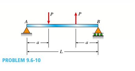
-10 The simple beam AB shown in the figure supports two equal concentrated loads P: one acting downward and the other upward.
Determine the angle of rotation
The equation for the angle of rotation
Answer to Problem 9.6.10P
The equation for the angle of rotation
Explanation of Solution
Given Information:
We have,
Length of the beam, AB =L
Concentrated Load, as P
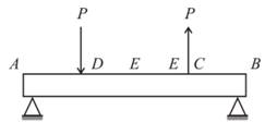
We have below diagram for
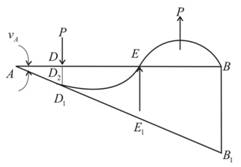
The diagram for deflection of center is below:
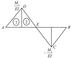
The bending moment:
The total area A is determined by first and second part of area as
So, first and second parts of area have the equations below.
Now, we can determine first moment area point C :
The angle of rotation for the point A:
The distance between D and
For point D, first moment area would be :
:
The deflection at download,
The symmetric deflection at the midpoint is 0.
Conclusion:
The equation for the angle of rotation
Want to see more full solutions like this?
Chapter 9 Solutions
Mechanics of Materials - MindTap Access


- The cantilever beam ACB shown in the figure has moments of inertia /, and I{in parts AC and CB, respectively. Using the method of superposition, determine the deflection 8Bat the free end due to the load P. Determine the ratio r of the deflection 8Bto the deflection S:at the free end of a prismatic cantilever with moment of inertia /] carrying the same load. Plot a graph of the deflection ratio r versus the ratio 12 //L of the moments of inertia. (Let /, II- vary from I to 5.)arrow_forward-18 The beam shown in the figure has a sliding support at A and a spring support at B, The sliding support permits vertical movement but no rotation. Derive the equation of the deflection curve and determine the deflection Bat end B due to the uniform load of intensity q. Use the second-order differential equation of the deflection curve.arrow_forwardThe horizontal beam ABC of an oil-well pump has the cross section shown in the figure. If the vertical pumping force acting at end C is 9 kips and if the distance from the line of action ofthat force to point B is 16 ft, what is the maximum bending stress in the beam due to the pumping force?arrow_forward
- -23 The beam shown in the figure has a sliding support at A and a roller support at B. The sliding support permits vertical movement but no rotation. Derive the equation of the deflection curve and determine the deflection Aat end A and also cat point C due to the uniform load of intensity q = P/ L applied over segment CB and load P at x = L / 3. Use the second-order differential equation of the deflection curve.arrow_forwardA temporary wood flume serving as a channel for irrigation water is shown in the figure. The vertical boards forming the sides of the flume are sunk in the ground, which provides a fixed support. The top of the flume is held by tic rods that are tightened so that there is no deflection of the boards at that point. Thus, the vertical boards may be modeled as a beam AB, supported and loaded as shown in the last part of the figure. Assuming that the thickness t of the boards is 1,5 in., the depth d of the water is 40 in., and the height h to the tie rods is 50 in., what is the maximum bending stress in the boards? Hint: The numerically largest bending moment occurs at the fixed support.arrow_forwardThe simple beam shown in the figure supports a concentrated load P acting at distance a from the left-hand support and distance h from the right-hand support. Determine the deflection SDat point D where the load is applied. (Obtain the solution by determining the strain energy of the beam and then using Castigliano's theorem.)arrow_forward
- The cross section of a bimetallic strip is shown in the figure. Assuming that the moduli of elasticity for metals A and B are EA=168 GPa and EB= 90 GPa, respectively, determine the smaller of the two section moduli for the beam. (Recall that section modulus is equal to bending moment divided by maximum bending stress.) In which material does the maximum stress occur?arrow_forwardA heavy object of weight W is dropped onto the midpoint of a simple beam AB from a height h (see figure). Obtain a formula for the maximum bending stress ^ma* due to tne filing weight in terms of h, st, and 5st, where it is the maximum bending stress and Sstis the deflection at the midpoint when the weight W acts on the beam as a statically applied load. Plot a graph of the ratio o"max/ö"it (that is, the ratio of the dynamic stress to the static stress) versus the ratio iifS^r(Let h/S^ vary from 0 to 10.)arrow_forwardThe tapered cantilever beam AB shown in the figure has a solid circular cross section. The diameters at the ends A and B are dAand dB= 2dA, respectively. Thus, the diameter d and moment of inertia / at distance v from the free end are, respectively, in which IAis the moment of inertia at end A of the beam. Determine the equation of the deflection curve and the deflection SAat the free end of the beam due to the load P.arrow_forward
- -3 The simple beam AB shown in the figure has moments 2M0and A/0 acting at the ends. Derive the equation of the deflection curve, and then determine the maximum deflection max Use the third-order differential equation of the deflection curve (the shear-force equation).arrow_forwardThe T-beam shown in the figure has cross-sectional dimensions: b = 210 mm, t = 16 mm, h = 300 mm, and A, = 280 mm. The beam is subjected to a shear force V = 68 kN. Determine the maximum shear stress tntijlin the web of the beam.arrow_forwardA beam supporting a uniform load of intensity q throughout its length rests on pistons at points A, C and B (sec figure). The cylinders are filled with oil and are connected by a tube so that the oil pressure on each piston is the same. The pistons at A and B have diameter d1and the piston at C has diameter D2. (a) Determine the ratio of d2to d1so that the largest bending moment in the beam is as small as possible. Under these optimum conditions, what is the largest bending moment Mmaxin the beam? What is the difference in elevation between point C and the end supports?arrow_forward
 Mechanics of Materials (MindTap Course List)Mechanical EngineeringISBN:9781337093347Author:Barry J. Goodno, James M. GerePublisher:Cengage Learning