Videos
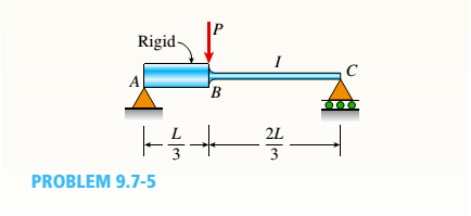
A beam ABC has a rigid segment from A to B and a flexible segment with moment of inertia / from B to C(see figure). A concentrated load P acts at point B.
Determine the angle of rotation SAof the rigidsegment, the deflection 8Bat point ß, and the maximum deflection 8.
The angle of rotation
Answer to Problem 9.7.5P
The angle of rotation
Explanation of Solution
Given Information:
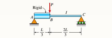
We have the beam ABC with rigid segment from point A to B and flexible segment with moment of inertia I from point B to C. A concentrated load P acts at Point B as shown in below figure.
We have,
Length of the beam as L
Moment of inertia as
Concentrated load at Point B = P
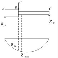
The shear force acting over beam can be shown below diagram.
The shear force working from point A to B is
We are taking derivative on both sides, we will get
Now for shear force working from point B to C is below.
According to boundary condition at
In above equation taking integration again,
And at 2nd Boundary conditions, x = L and v = 0.
And at 3rd Boundary conditions,
For maximum deflection,
So we will calculate maximum deflection as below,
The angle of rotation,
Deflection,
But the maximum deflection would be,
Conclusion:
The angle of rotation
Want to see more full solutions like this?
Chapter 9 Solutions
Mechanics of Materials - Text Only (Looseleaf)


- Beam ABC is fixed at support A and rests (at point B) upon the midpoint of beam DE (see part a of the figure). Thus, beam, ABC may be represented as a propped cantilever beam with an overhang BC and a linearly elastic support of stiffness k at point B (see part b of the figure). The distance from A to B is L = 10 ft, the distance from B to C is L/2 = 5 ft, and the length of beam DE is L = 10 ft. Both beams have the same flexural rigidity EI. A concentrated load P = 1700 lb acts at t lie free end of beam ABC. Determine the reactions RA, RB+ and MAfor beam ABC. Also, draw the shear-force and bending-moment diagrams for beam ABC, labeling all critical ordinates.arrow_forward(a) A simple beam AB with length L and height h supports a uniform load of intensity q (see the figure part a). Obtain a formula for the curvature shortening A of this beam. Also, obtain a formula for the maximum bending stress b in the beam due to the load q. Now assume that the ends of the beam are pinned so that curvature shortening is prevented and a horizontal force H develops at the supports (see the figure part b). Obtain a formula for the corresponding axial tensile stress t . Using the formulas obtained in parts (a) and (b), calculate the curvature shortening , the maximum bending stress b, and the tensile stress t for the following steel beam: length L = 3m, height h = 300 mm, modulus of elasticity E = 200 GPa, and moment of inertia I = 36 x 106 mm4. Also, the load on the beam has intensity q = 25 kN/m. Compare the tensile stress tproduced by the axial forces with the maximum bending stress bproduced by the uniform load.arrow_forwardBeam ABCD represents a reinforced-concrete foundation beam that supports a uniform load of intensity q1= 3500 lb/ft (see figure). Assume that the soil pressure on the underside of the beam is uniformly distributed with intensity q2 Find the shear force VBand bending moment MBat point B. Find the shear force Vmand bending moment M at the midpoint of the beam.arrow_forward
- A simple beam of length L = 5 m carries a uniform load of intensity q = 5,8 kN/m and a concentrated load 22.5 kN (see figure). (a) Assuming tra]]ow = 110 MPa, calculate the required section modulus S. Then select the most economical wide-flange beam (W shape) from Table F-l(b) in Appendix F, and recalculate S, taking into account the weight of the beam. Select a new beam if necessary. (b) Repeat part (a), but now assume that the design requires that the W shape must be used in weak axis bending (i.e., it must bend about the 2-2 (or y) axis of the cross section).arrow_forwardA propped cantilever beam of length L = 54 in. with a sliding support supports a uniform load of intensity q (see figure). The beam is made of steel {<7y = 36 ksi) and has a rectangular cross section of width/) = 4.5 in. and height h = 6.0 in. What load intensity q will produce a fully plastic condition in the beam?arrow_forwardA cantilever beam AB of length L = 6.5 ft supports a trapezoidal distributed load of peak intensity 4, and minimum intensity q/2tthat includes the weight of the beam (see figure). The beam is a steel W 12 × 14 wide-flange shape (see Table F-l(a), Appendix F). Calculate the maximum permissible load q based upon (a) an allowable bending stress eallow = 18 ksi and (b) an allowable shear stress eallow = 7,5 ksi. Note: Obtain the moment of inertia and section modulus of the beam from Table F-l(a).arrow_forward
- A simple beam AB is subjected to a load in the form of a couple M0 acting at end B (see figure). Determine the angles of rotation A and B at the supports and the deflection at the midpoint.arrow_forwardA simple beam ABC having rectangular cross sections with constant height A and varying width bxsupports a concentrated load P acting at the midpoint (see figure). How should the width bxvary as a function of x in order to have a fully stressed beam? (Express bxin terms of the width bgat the midpoint of the beam.)arrow_forwardA simply supported beam (E = 1600 ksi) is loaded by a triangular distributed load from A to C(see figure). The load has a peak intensity q0= 10 lb/ ft, and the deflection is known to be 0.01 in, at point C. The length of the beam is 12 ft, and the ratio of the height to the width of the cross section is (h:b) 2:1, Find the height h; and width h of the cross section of the beam.arrow_forward
- The overhanging beam A BCD supports two concentrated loads P and Q (see figure), For what ratio PIQ will the deflection at point B be zero? For what ratio will the deflection at point D be zero? If Q is replaced by a uniform load with intensity q (on the overhang), repeat parts (a) and (b), but find ratio Pl(qa).arrow_forwardThe beam AB shown in the figure is simply supported at A and B and supported on a spring of stiffness k at its midpoint C. The beam has flexural rigidity EI and length IL. What should be the stiffness k of the spring in order that the maximum bending moment in the beam (due to the uniform load) will have the smallest possible value?arrow_forwardA beam with a channel section is subjected to a bending moment M having its vector at an angle 0 to the 2 axis (see figure). Determine the orientation of the neutral axis and calculate the maximum tensile stress et and maximum compressive stress ecin the beam. Use the following data: C 8 × 11.5 section, M = 20 kip-in., tan0=l/3. See Table F-3(a) of Appendix F for the dimensions and properties of the channel section.arrow_forward
 Mechanics of Materials (MindTap Course List)Mechanical EngineeringISBN:9781337093347Author:Barry J. Goodno, James M. GerePublisher:Cengage Learning