Concept explainers
Videos
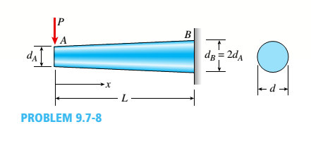
The tapered cantilever beam AB shown in the figure has a solid circular cross section. The diameters at the ends A and B are dAand dB= 2dA, respectively. Thus, the diameter d and moment of inertia / at distance v from the free end are, respectively,
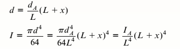 in which IAis the moment of inertia at end A of the beam.
Determine the equation of the deflection curve and the deflection SAat the free end of the beam due to the load P.
The equation for the deflection curve and the deflection
Answer to Problem 9.7.8P
The equation for the deflection curve and the deflection
Explanation of Solution
Given Information:
We have,
Length of the tapered cantilever beam AB, L
Load at point A as P
Diameter at point A,
Diameter at point B,
Moment of inertia, I
The bending moment is
So, the 2nd degree diffrential equation would be,
In the above equation, taking integration on both sides :
According to boundary condition at x=L,
In above equation taking integration again,
And at 2nd Boundary conditions, x = L and v = 0.
At x = 0, then
At point A, the deflection would be below.
Conclusion:
The answers are calculated according to deflection and deflection curve.
Want to see more full solutions like this?
Chapter 9 Solutions
Mechanics of Materials - Text Only (Looseleaf)


- The hollow box beam shown in the figure is subjected to a bending moment M of such magnitude that the flanges yield but the webs remain linearly elastic. (a) Calculate the magnitude of the moment M if the dimensions of the cross section are A = 15 in., A] = 12.75 in., h = 9 in., and ey =7.5 in. Also, the yield stress is eY = 33 ksi. (b) What percent of the moment M is produced by the elastic core?arrow_forwardA simply supported beam (E = 1600 ksi) is loaded by a triangular distributed load from A to C(see figure). The load has a peak intensity q0= 10 lb/ ft, and the deflection is known to be 0.01 in, at point C. The length of the beam is 12 ft, and the ratio of the height to the width of the cross section is (h:b) 2:1, Find the height h; and width h of the cross section of the beam.arrow_forward-22 Derive the equations of the deflection curve for a simple beam AB with a distributed load of peak intensity q0acting over the left-hand half of the span (see figure). Also, determine the deflection cat the midpoint of the beam. Use the second-order differential equation of the deflection curve.arrow_forward
- -20 Derive the equations of the deflection curve for a cantilever beam AB carrying a uniform load of intensity q over part of the span (see figure). Also, determine the deflection Bat the end of the beam. Use the second-order differential equation of the deflection curve.arrow_forwardA hollow box beam with height h = 16 in,, width h = 8 in,, and constant wall thickness r = 0.75 LiL is shown in the figure. The beam is constructed of steel with yield stress ty = 32 ksi. Determine the yield moment My, plastic moment A/p, and shape factor.arrow_forwardA tapered cantilever beam A B supports a concentrated load P at the free end (see figure). The cross sections of the beam are rectangular with constant width A, depth d Aat support A, and depth ds= ^dJ2 at the support. Thus, the depth d and moment of inertia / at distance x from the free end are, respectively, in which / 4 is the moment of inertia at end A of the beam. Determine the equation of the deflection curve and the deflection S 4at the free end of the beam due to the load P.arrow_forward
- -21 Derive the equations of the deflection curve for a cantilever beam AB supporting a distributed load of peak intensity q0acting over one-half of the length (see figure). Also, obtain formulas for the deflections Band cat points B and C, respectively Use the second-order differentia] equation of the deflection curve.arrow_forwardA cantilever beam of a length L = 2.5 ft has a rectangular cross section {b = 4in,, h = Sin,) and modulus E = 10,000 ksi. The beam is subjected to a linearly varying distributed load with a peak intensity qQ= 900 lb/ft. Use the method of superposition and Cases 1 and 9 in Table H-l to calculate the deflection and rotation at B.arrow_forwardA cantilever beam AB of length L = 6 It is constructed of a W 8 x 21 wide-flange section (see figure), A weight W = 1500 lb falls through a height h = 0.25 in. onto the end of the beam. Calculate the maximum deflection £m.iy of the end of the beam and the maximum bendini* stress *rm,vdue to the falling weight, (Assume E = 30 X 10 psi,)arrow_forward
- A simple beam AB of length L and height /; undergoes a temperature change such that the bottom of the beam is at temperature 7™, and the top of the beam is at temperature Tx(see figure). Determine the equation of the deflection curve of the beam, the angle of rotation 9Aat the left-hand support, and the deflection 8mjLXat the midpoint.arrow_forwardA cantilever beam AB of length L = 6.5 ft supports a trapezoidal distributed load of peak intensity 4, and minimum intensity q/2tthat includes the weight of the beam (see figure). The beam is a steel W 12 × 14 wide-flange shape (see Table F-l(a), Appendix F). Calculate the maximum permissible load q based upon (a) an allowable bending stress eallow = 18 ksi and (b) an allowable shear stress eallow = 7,5 ksi. Note: Obtain the moment of inertia and section modulus of the beam from Table F-l(a).arrow_forwardA cantilever beam has a length L = 12 ft and a rectangular cross section (b = 16 in., h = 24 in.), A linearly varying distributed load with peak intensity q0acts on the beam, (a) Find peak intensity q0if the deflection at joint B is known to be 0.18 in. Assume that modulus E = 30,000 ksi. (b) Find the location and magnitude of the maximum rotation of the beam.arrow_forward
 Mechanics of Materials (MindTap Course List)Mechanical EngineeringISBN:9781337093347Author:Barry J. Goodno, James M. GerePublisher:Cengage Learning