Videos
Consider a Mach 4 airflow at a pressure of 1 atm. We wish to slow this flow to subsonic speed through a system of shock waves with as small a loss in total pressure as possible. Compare the loss in total pressure for the following three shock systems:
a. A single normal shock wave
b. An oblique shock with a deflection angle of
c. An oblique shock with a deflection angle of
From the results of (a), (b), and (c), what can you induce about the efficiency of the various shock systems?
(a)
The comparison in total pressure loss for the single normal shock wave.
Answer to Problem 9.8P
The loss in pressure is
Explanation of Solution
Given:
The Mach number is
The pressure is
Formula used:
The expression for
The expression for
The expression for loss in pressure is given as,
Calculation:
The pressure
The pressure
The loss in pressure can be calculated as,
Conclusion:
Therefore, the loss in pressure is
(b)
The comparison in pressure for an oblique shock with a deflection angle of
Answer to Problem 9.8P
The loss in pressure is
Explanation of Solution
Given:
The Mach number is
The pressure is
The deflection angle of oblique shock wave is
Formula used:
The expression for
The expression for
The expression for
The expression for loss in pressure is given as,
Calculation:
From
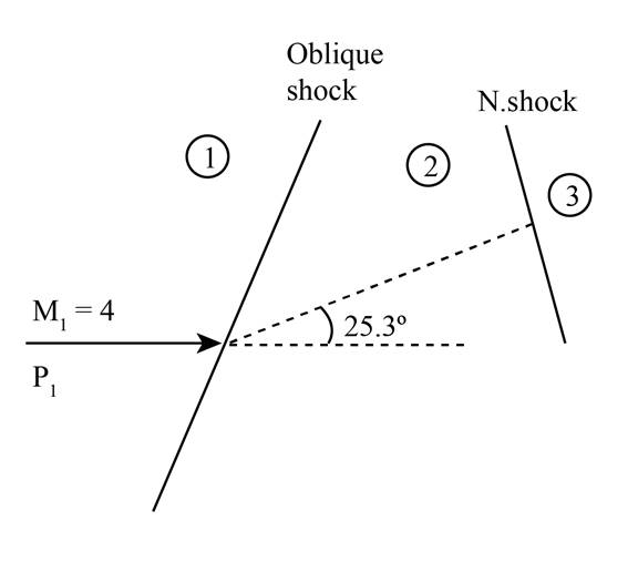
Figure (1)
The Mach number
The pressure ratio for Mach number
From appendix B
The Mach number
The pressure ratio for Mach number
The pressure
The pressure loss can be calculated as,
Conclusion:
Therefore, the loss in pressure is
(c)
The comparison in pressure for the an oblique shock with a deflection angle of
Answer to Problem 9.8P
The loss in pressure is
Explanation of Solution
Given:
The Mach number is
The pressure is
The deflection angle of second oblique shock wave is
Formula used:
The expression for the Mach number
The expression for Mach number
The expression for the pressure
The expression for loss in pressure is given as,
Calculation:
From
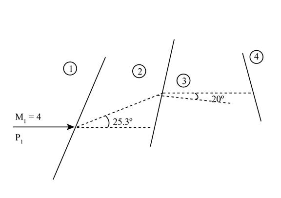
Figure (2)
The Mach number
The pressure ratio for Mach number from appendix B is given as,
Refer to appendix B
The Mach number
The pressure ratio for Mach number
The pressure
The pressure loss can be calculated as,
From a, b and c it is clear that the most efficient way to decrease supersonic flow to subsonic flow is through a combination of supersonic diffuser and then normal shock wave at the end.
Conclusion:
Therefore, the loss in pressure is
Want to see more full solutions like this?
Chapter 9 Solutions
Fundamentals of Aerodynamics


- A uniform supersonic airflow traveling at Mach 2.0 passes over a wedge (Fig. 10E.1). An oblique shock, making an angle of 40° with the flow direction, is attached to the wedge under these flow conditions. If the static pressure and temperature in the uniform flow are, respectively, 20 kPa and −10 °C, determine the static pressure and temperature behind the wave, the Mach number of the flow passing over the wedge, and the wedge half-angle.arrow_forwardThe velocity ratio (v1/v2) of an isentropic flow through a supersonic wind tunnel is 0.615. if the mach number at the tunnels entry section is 0.95 find the value of mach number at the exitarrow_forwardA uniform supersonic flow of air at Mach 3.8, with a stagnation pressure of 5.0 MPa and stagnationtemperature of 1100 K, expands around a 23o convex corner. Determine the downstream Macharrow_forward
- Air flows into a converging duct, and a normal shock stands at the exit of the duct. Downstream of the shock, the Mach number is 0.54. If p2/p1 = 2, compute the Mach number at the entrance of the duct and the area ratio A1/A2.arrow_forwardQUESTION 1 The Mach number behind a normal shock wave is 0.4752. What is the Mach number infront of the wave?arrow_forwardAir enters a converging–diverging nozzle of a supersonic wind tunnel at 150 psia and 100°F with a low velocity. The flow area of the test section is equal to the exit area of the nozzle, which is 5 ft2. Calculate the pressure, temperature, velocity, and mass flow rate in the test section for a Mach number Ma = 2. Explain why the air must be very dry for this application.arrow_forward
- 1. Air having a reservoir pressure of 30 psia and density of 0.15 lb/ft is accelerated to a Mach number of 1.6. Find the static pressure, density, and temperature at this Mach number. 2. Consider the flow of air through a supersonic nozzle. The reservoir pressure and temperature are 5 atm and 500 K, respectively. If the Mach number at the nozzle exit is 3, calculate the exit pressure , temperature, and density. 4. A supersonic nozzle is a convergent-divergent duct , which is fed by a large reservoir at the inlet to the nozzle. In the reservoir of the nozzle, the pressure and temperature are 10atm and 550°R , respectively. At the nozzle exit, the pressure is 1 atm. Calculate the temperature and density of the flow at the exit. Assume the flow is isentropic and , of course, compressible. 3. The mass flow of air through a supersonic nozzle is 1.5 lbm/s. The exit velocity is 1,500 ft/sec, and the reservoir temperature and pressure are 1,000 'R and 7 atm , respectively. Calculate the…arrow_forwardSupersonic air at Ma1 = 2.0 and 230 kPa flows parallel to a flat wall that suddenly expands by ? = 10° . Ignoring any effects caused by the boundary layer along the wall, calculate downstream Mach number Ma2 and pressure P2.arrow_forwardWhen a pitot-static tube is placed in a supersonic flow, the probe reads P = 190 kPa and P = 150 kPa. If the stagnation temperature is 400 K, estimate the freestream Mach number and velocity.arrow_forward
- Engineers call the supersonic combustion in a scramjetengine almost miraculous, “like lighting a match in a hurricane.”Figure C9.8 is a crude idealization of the engine.Air enters, burns fuel in the narrow section, then exits, all at supersonic speeds. There are no shock waves. Assume areasof 1 m2 at sections 1 and 4 and 0.2 m2 at sections 2 and3. Let the entrance conditions be Ma1 = 6, at 10,000 mstandard altitude. Assume isentropic fl ow from 1 to 2,frictionless heat transfer from 2 to 3 with Q = 500 kJ/kg,and isentropic fl ow from 3 to 4. Calculate the exit conditionsand the thrust produced.arrow_forwardAir enters a convergent-divergent nozzle at a temperature of 400K and a pressure of 10 atm. The throat area is one-half that of the discharge of the divergent section. Assuming the Mach number in the throat is 0.75, what are the values of the following quantities at the throat: pressure(atm), temperature(K), linear velocity(m/s), density(kg/m3), and mass velocity(kg/m2s)? What are the values of p*(in atm), T*(in K), u*(in m/s), and G* (in kg/m2.s) corresponding to reservoir conditions? Write your answers according to order of properties asked.arrow_forwardAn aircraft is flying at supersonic speed. At a component of an aircraft where the flow is perpendicular, the density ratio is 5. Solve for: a.Mach Number Downstream b. Pressure Ratio c. Temperature Ratio d. Mach Number upstreamarrow_forward
 Elements Of ElectromagneticsMechanical EngineeringISBN:9780190698614Author:Sadiku, Matthew N. O.Publisher:Oxford University Press
 Mechanics of Materials (10th Edition)Mechanical EngineeringISBN:9780134319650Author:Russell C. HibbelerPublisher:PEARSON
 Thermodynamics: An Engineering ApproachMechanical EngineeringISBN:9781259822674Author:Yunus A. Cengel Dr., Michael A. BolesPublisher:McGraw-Hill Education
 Control Systems EngineeringMechanical EngineeringISBN:9781118170519Author:Norman S. NisePublisher:WILEY
 Mechanics of Materials (MindTap Course List)Mechanical EngineeringISBN:9781337093347Author:Barry J. Goodno, James M. GerePublisher:Cengage Learning
 Engineering Mechanics: StaticsMechanical EngineeringISBN:9781118807330Author:James L. Meriam, L. G. Kraige, J. N. BoltonPublisher:WILEY