
Mechanics Of Materials - Si Version
7th Edition
ISBN: 9789814595247
Author: Ferdinand Beer
Publisher: Mcgraw-Hill
expand_more
expand_more
format_list_bulleted
Concept explainers
Videos
Textbook Question
Chapter 9.4, Problem 81P
Use the method of superposition to solve the following problems and assume that the flexural rigidity El of each beam is constant.
9.81 and 9.82 For the uniform beam shown, determine the reaction at each of the three supports.
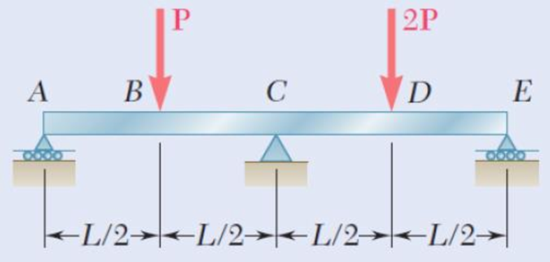
Fig. P9.81
Expert Solution & Answer
Want to see the full answer?
Check out a sample textbook solution
Students have asked these similar questions
Problem 2. (a) Draw the moment diagram for the
beam. (b) Observing the direction of load and sign of
the moment diagram, and knowledge of the boundary
conditions, sketch the elastic curve, that is, the vertical
deflection of the axial line thru the centroid of the
beam section, (c) Using integration, determine the
equation of the elastic curve for the beam using the x
coordinate that is valid for 0 < x < L/2. (d) Specify the
slope at A and the beam's maximum deflection. El is
constant. For parts (a) and (b), model only one-half of
the beam, from x=0 to x=L/2, and use the symmetry
dv
boundary condition, slope = 0, at the vertical line
of symmetry at x=L/2.
dx
X
NA
B
6.36 Using Castigliano's method on the wire form shown determine the vertical
deflection of point A considering bending only. The rigidity of the cross sec-
tion is El.
R
Problem 6.36
B
For the beam shown:
1) Determine the reactions in terms of P.
Modulus - E
Area Moment of Inertia - I
За
Chapter 9 Solutions
Mechanics Of Materials - Si Version
Ch. 9.2 - In the following problems assume that the flexural...Ch. 9.2 - In the following problems assume that the flexural...Ch. 9.2 - In the following problems assume that the flexural...Ch. 9.2 - 9.1 through 9.4 For the loading shown, determine...Ch. 9.2 - 9.5 and 9.6 For the cantilever beam and loading...Ch. 9.2 - 9.5 and 9.6 For the cantilever beam and loading...Ch. 9.2 - For the beam and loading shown, determine (a) the...Ch. 9.2 - For the beam and loading shown, determine (a) the...Ch. 9.2 - Knowing that beam .AB is a W10 33 rolled shape...Ch. 9.2 - Knowing that beam AB is an S200 34 roiled shape...
Ch. 9.2 - For the beam and loading shown, (a) express the...Ch. 9.2 - (a) Determine the location and magnitude of the...Ch. 9.2 - For the beam and loading shown, determine the...Ch. 9.2 - Knowing that beam AE is a W360 101 rolled shape...Ch. 9.2 - For the beam and loading shown, knowing that a = 2...Ch. 9.2 - Knowing that beam AE is an S200 27.4 rolled shape...Ch. 9.2 - For the beam and loading shown, determine (a) the...Ch. 9.2 - For the beam and loading shown, determine (a) the...Ch. 9.2 - 9.19 through 9.22 For the beam and loading shown,...Ch. 9.2 - 9.19 through 9.22 For the beam and loading shown,...Ch. 9.2 - 9.19 through 9.22 For the beam and loading shown,...Ch. 9.2 - 9.19 through 9.22 For the beam and loading shown,...Ch. 9.2 - For the beam shown, determine the reaction at the...Ch. 9.2 - For the beam shown, determine the reaction at the...Ch. 9.2 - 9.25 through 9.28 Determine the reaction at the...Ch. 9.2 - 9.25 through 9.28 Determine the reaction at the...Ch. 9.2 - Prob. 27PCh. 9.2 - 9.25 through 9.28 Determine the reaction at the...Ch. 9.2 - 9.29 and 9.30 Determine the reaction at the roller...Ch. 9.2 - 9.29 and 9.30 Determine the reaction at the roller...Ch. 9.2 - 9.37 and 9.32 Determine the reaction at the roller...Ch. 9.2 - 9.31 and 9.32 Determine the reaction at the roller...Ch. 9.2 - Prob. 33PCh. 9.2 - 9.33 and 9.34 determine the reaction at A and draw...Ch. 9.3 - 9.35 and 9.36 For the beam and loading shown,...Ch. 9.3 - 9.35 and 9.36 For the beam and loading shown,...Ch. 9.3 - 9.37 and 9.38 For the beam and loading shown,...Ch. 9.3 - 9.37 and 9.38 For the beam and loading shown,...Ch. 9.3 - 9.39 and 9.40 For the beam and loading shown,...Ch. 9.3 - 9.39 and 9.40 For the beam and loading shown,...Ch. 9.3 - 9.41 and 9.42 For the beam and loading shown,...Ch. 9.3 - 9.41 and 9.42 For the beam and loading shown (a)...Ch. 9.3 - For the beam and loading shown, determine (a) the...Ch. 9.3 - For the beam and loading shown, determine (a) the...Ch. 9.3 - For the timber beam and loading shown, determine...Ch. 9.3 - For the beam and loading shown, determine (a) the...Ch. 9.3 - For the beam and loading shown, determine (a) the...Ch. 9.3 - For the beam and loading shown, determine (a) the...Ch. 9.3 - 9.49 and 9.50 For the beam and loading shown,...Ch. 9.3 - 9.49 and 9.50 For the beam and loading shown,...Ch. 9.3 - 9.51 and 9.52 For the beam and loading shown,...Ch. 9.3 - 9.49 and 9.50 For the beam and loading shown,...Ch. 9.3 - For the beam and loading shown, determine (a) the...Ch. 9.3 - For the beam shown, and knowing that P = 40 kN,...Ch. 9.3 - 9.55 and 9.56 For the beam and loading shown, (a)...Ch. 9.3 - 9.55 and 9.56 For the beam and loading shown, (a)...Ch. 9.3 - For the beam and loading shown, determine (a) the...Ch. 9.3 - For the beam and loading shown, determine (a) the...Ch. 9.3 - Prob. 59PCh. 9.3 - 9.59 through 9.62 For the beam and loading...Ch. 9.3 - Prob. 61PCh. 9.3 - 9.59 through 9.62 For the beam and loading...Ch. 9.3 - The rigid bars BF and DH are welded to the...Ch. 9.3 - The rigid bar DEF is welded at point D to the...Ch. 9.4 - Use the method of superposition to solve the...Ch. 9.4 - Use the method of superposition to solve the...Ch. 9.4 - Use the method of superposition to solve the...Ch. 9.4 - Use the method of superposition to solve the...Ch. 9.4 - Use the method of superposition to solve the...Ch. 9.4 - Use the method of superposition to solve the...Ch. 9.4 - Use the method of superposition to solve the...Ch. 9.4 - Use the method of superposition to solve the...Ch. 9.4 - Use the method of superposition to solve the...Ch. 9.4 - Use the method of superposition to solve the...Ch. 9.4 - Use the method of superposition to solve the...Ch. 9.4 - Use the method of superposition to solve the...Ch. 9.4 - Use the method of superposition to solve the...Ch. 9.4 - Use the method of superposition to solve the...Ch. 9.4 - Use the method of superposition to solve the...Ch. 9.4 - Use the method of superposition to solve the...Ch. 9.4 - Use the method of superposition to solve the...Ch. 9.4 - Use the method of superposition to solve the...Ch. 9.4 - Use the method of superposition to solve the...Ch. 9.4 - Prob. 84PCh. 9.4 - Use the method of superposition to solve the...Ch. 9.4 - Use the method of superposition to solve the...Ch. 9.4 - Use the method of superposition to solve the...Ch. 9.4 - Use the method of superposition to solve the...Ch. 9.4 - Use the method of superposition to solve the...Ch. 9.4 - Use the method of superposition to solve the...Ch. 9.4 - Use the method of superposition to solve the...Ch. 9.4 - Use the method of superposition to solve the...Ch. 9.4 - Use the method of superposition to solve the...Ch. 9.4 - Use the method of superposition to solve the...Ch. 9.5 - 9.95 through 9.98 For the uniform cantilever beam...Ch. 9.5 - Prob. 96PCh. 9.5 - 9.95 through 9.98 For the uniform cantilever beam...Ch. 9.5 - 9.95 through 9.98 For the uniform cantilever beam...Ch. 9.5 - 9.99 and 9.100 For the uniform cantilever beam and...Ch. 9.5 - 9.99 and 9.100 For the uniform cantilever beam and...Ch. 9.5 - For the cantilever beam and loading shown,...Ch. 9.5 - Prob. 102PCh. 9.5 - Prob. 103PCh. 9.5 - Prob. 104PCh. 9.5 - Prob. 105PCh. 9.5 - For the cantilever beam and loading shown,...Ch. 9.5 - Two cover plates are welded to the rolled-steel...Ch. 9.5 - Two cover plates are welded to the rolled-steel...Ch. 9.5 - 9.109 through 9.114 For the prismatic beam and...Ch. 9.5 - Prob. 110PCh. 9.5 - Prob. 111PCh. 9.5 - Prob. 112PCh. 9.5 - Prob. 113PCh. 9.5 - Prob. 114PCh. 9.5 - Prob. 115PCh. 9.5 - 9.115 and 9.116 For the beam and loading shown,...Ch. 9.5 - Prob. 117PCh. 9.5 - 9.118 and 9.119 For the beam and loading shown,...Ch. 9.5 - Prob. 119PCh. 9.5 - Prob. 120PCh. 9.5 - Prob. 121PCh. 9.5 - Prob. 122PCh. 9.5 - Prob. 123PCh. 9.5 - Prob. 124PCh. 9.6 - 9.125 through 9.128 For the prismatic beam and...Ch. 9.6 - Prob. 126PCh. 9.6 - Prob. 127PCh. 9.6 - Prob. 128PCh. 9.6 - 9.129 and 9.130 For the beam and loading shown,...Ch. 9.6 - Prob. 130PCh. 9.6 - For the timber beam and loading shown, determine...Ch. 9.6 - Prob. 132PCh. 9.6 - For the beam and loading shown, determine (a) the...Ch. 9.6 - Prob. 134PCh. 9.6 - Prob. 135PCh. 9.6 - Knowing that the beam AD is made of a solid steel...Ch. 9.6 - Prob. 137PCh. 9.6 - For the beam and loading shown, determine (a) the...Ch. 9.6 - Prob. 139PCh. 9.6 - For the beam and loading shown, determine the...Ch. 9.6 - Prob. 141PCh. 9.6 - Prob. 142PCh. 9.6 - Prob. 143PCh. 9.6 - Prob. 144PCh. 9.6 - Prob. 145PCh. 9.6 - For the beam and loading shown, determine (a) the...Ch. 9.6 - Prob. 147PCh. 9.6 - Prob. 148PCh. 9.6 - Prob. 149PCh. 9.6 - Prob. 150PCh. 9.6 - 9.151 and 9.152 For the beam and loading shown,...Ch. 9.6 - Prob. 152PCh. 9.6 - Prob. 153PCh. 9.6 - Prob. 154PCh. 9.6 - Prob. 155PCh. 9.6 - Fig. P9.155 and P9.156 9.156 For the beam and...Ch. 9 - For the loading shown, determine (a) the equation...Ch. 9 - Prob. 158RPCh. 9 - For the beam and loading shown, determine (a) the...Ch. 9 - Determine the reaction at A and draw the bending...Ch. 9 - For the beam and loading shown, determine (a) the...Ch. 9 - For the beam and loading shown, determine (a) the...Ch. 9 - Beam CE rests on beam AB as shown. Knowing that a...Ch. 9 - The cantilever beam BC is attached to the steel...Ch. 9 - For the cantilever beam and loading shown,...Ch. 9 - Knowing that P = 4 kips, determine (a) the slope...Ch. 9 - For the beam and loading shown, determine (a) the...Ch. 9 - Determine the reaction at the roller support and...
Knowledge Booster


Learn more about
Need a deep-dive on the concept behind this application? Look no further. Learn more about this topic, mechanical-engineering and related others by exploring similar questions and additional content below.Similar questions
- An overhang beam with negligible weight is loaded as shown. Knowing that the flexural rigidity of the beam is El = 2 × 10⁵ kNm², (a) Reactions at A and B (a) determine the reactions at supports A and B, (b) derive the elastic (b) section AB curve for section AB, (c) derive the elastic curve for section BC, and v = (d) determine the deflection at point C. v = (c) section BC v' = 2 kN/m v = (d) m marrow_forwardPROBLEM 4.The beam AB consisting of a cast iron plate of uniform thickness, b, and length, L, is to support the distributed load w(x) shown a) Knowing that the beam is to be of constant strength (fully stressed beam), express h in terms of x, L and ho. b) Determine the smallest value of ho if L=800 mm, b=25 mm, wo=300 kN/m and oall=200 MPa. w-=WoCos(ITX/2L) A ho Barrow_forwardFor the beam and loading shown, use the double-integration method to determine (a) the equation of the elastic curve for the beam, (b) the location of the maximum deflection, and (c) the maximum beam deflection. Assume that El is constant for the beam. Let w = 13 kN/m, L = 4.0 m, E = 180 GPa, and I = 130 x 106 mm“. B L Answer: (b) х %3 m (c) Vmax mmarrow_forward
- For the uniform beam shown, determine (a) the reaction at A, (b) the reaction at B.arrow_forward3. Determine the location and magnitude of the maximum deflection of the beam shown using: a. Double-integration Method b. Moment-Area Method c. Conjugate Beam Method 250 kN 6 m El = constant E = 200 GPa I = 462 (10*) mm*arrow_forwardProblem 3. (a) Draw the moment diagram for the beam. (b) Observing the direction of load and sign of the moment diagram, and knowledge of the boundary conditions, sketch the elastic curve, that is, the vertical deflection of the axial line thru the centroid of the beam section, (c) Determine the equation of the elastic curve for the beam using the x coordinate. (d) Specify the slope at A and the maximum deflection. El is constant. Mo L Barrow_forward
- 7.52 Determine the reactions on the beam at A and B. 2 kN/m A -4 m- B Problem 7.52 -2 m 3 kN/marrow_forward2. For the beam shown: a. Draw the free-body diagram of the beam. b. Determine the reactions at the supports. 1.8 m | 1.8m | 1¹ 4 0.80 KN 1.5m₂ 2.1m 1.38 kN 25⁰arrow_forwardThe load on the beam shown increases uniformly from 0 at point A to w = 63 N/m at point B over a length of L= 26 meters. Determine the magnitude of the support reaction at point B. Carrow_forward
- AC B P C. Fig. 4.57 Problem Fig. 4.55 Problems 4.7 and 4.8 Problem 4.11 A Problem 4.8 Reconsider the L-shaped beam illustrated in hinged to the wal Fig. 4.55. This time, assume that the applied force P has 2 mmnd it weighs components in the positive x and positive z directions such that P= P,i + Pj. Determine the reactions generated at the fixed end of the beam in terms of a, b, P. and P of the beam and it attached to the bea the horizontal. At t Answers: RA P(-X): RAV 0: RA-P.(-) wall. A load that w such that its gravity bP:(+v): M -a: P(-v): MA -bP.(- load of the same wei nOnt Barrow_forward2. A cover-plate beam is made up of an I-Beam section with 300 mm x 12 mm plates attached to the top and bottom flanges and is fastened by two rows of 20 mm rivets. The beam is simply supported over a span of 6m and carries a uniformly distributed load of 270 kN/m including its own weight. a. Determine the distance from the centroid of the cover plate to the neutral axis of the built-up section. b. Determine the moment of inertia of the built-up section about its neutral axis. c. Determine the maximum flexural stress of the built-up section. 200 mm 30 mm 310 mm 30 mm 30 mmarrow_forwardA large number of uniform and identical cantilever beams, each 1 m long and 146 N / m in weight, are used to support pipes. Consider that the length of the tubes acting under a typical ABCD beam is 1.2 m. And that tubes B and C, plus their contents, weigh 365 N / m and 510 N / m, respectively, determine the reactions at the end set in A, of the cantilever beams.arrow_forward
arrow_back_ios
SEE MORE QUESTIONS
arrow_forward_ios
Recommended textbooks for you
 Elements Of ElectromagneticsMechanical EngineeringISBN:9780190698614Author:Sadiku, Matthew N. O.Publisher:Oxford University Press
 Mechanics of Materials (10th Edition)Mechanical EngineeringISBN:9780134319650Author:Russell C. HibbelerPublisher:PEARSON
 Thermodynamics: An Engineering ApproachMechanical EngineeringISBN:9781259822674Author:Yunus A. Cengel Dr., Michael A. BolesPublisher:McGraw-Hill Education
 Control Systems EngineeringMechanical EngineeringISBN:9781118170519Author:Norman S. NisePublisher:WILEY
 Mechanics of Materials (MindTap Course List)Mechanical EngineeringISBN:9781337093347Author:Barry J. Goodno, James M. GerePublisher:Cengage Learning
 Engineering Mechanics: StaticsMechanical EngineeringISBN:9781118807330Author:James L. Meriam, L. G. Kraige, J. N. BoltonPublisher:WILEY
Elements Of Electromagnetics
Mechanical Engineering
ISBN:9780190698614
Author:Sadiku, Matthew N. O.
Publisher:Oxford University Press
Mechanics of Materials (10th Edition)
Mechanical Engineering
ISBN:9780134319650
Author:Russell C. Hibbeler
Publisher:PEARSON
Thermodynamics: An Engineering Approach
Mechanical Engineering
ISBN:9781259822674
Author:Yunus A. Cengel Dr., Michael A. Boles
Publisher:McGraw-Hill Education
Control Systems Engineering
Mechanical Engineering
ISBN:9781118170519
Author:Norman S. Nise
Publisher:WILEY
Mechanics of Materials (MindTap Course List)
Mechanical Engineering
ISBN:9781337093347
Author:Barry J. Goodno, James M. Gere
Publisher:Cengage Learning
Engineering Mechanics: Statics
Mechanical Engineering
ISBN:9781118807330
Author:James L. Meriam, L. G. Kraige, J. N. Bolton
Publisher:WILEY
Solids: Lesson 53 - Slope and Deflection of Beams Intro; Author: Jeff Hanson;https://www.youtube.com/watch?v=I7lTq68JRmY;License: Standard YouTube License, CC-BY