
Concept explainers
Videos
Use the method of superposition to solve the following problems and assume that the flexural rigidity El of each beam is constant.
9.90 Before the load P was applied, a gap, δ0 = 0.5 mm, existed between the cantilever beam AC and the support at B. Knowing that E = 200 GPa, determine the magnitude of P for which the deflection at C is 1 mm.
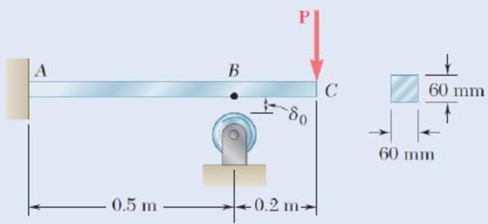
Fig. P9.90
Find the magnitude of load P for the given condition using superposition method.
Answer to Problem 90P
The magnitude of load P in the beam is
Explanation of Solution
Given information:
The gap at the point B is
The modulus of elasticity of the material is
The size of the square cross section is
The deflection at point C is
Calculation:
Find the moment of inertia of the square cross section (I) using the relation.
Here, the size of the square cross section is a.
Substitute 60 mm for a.
Consider the portion AB of the beam.
The load P at point C will be converted into a load and moment at point B.
Show the free-body diagram of the superimposed beam AB as in Figure 1.
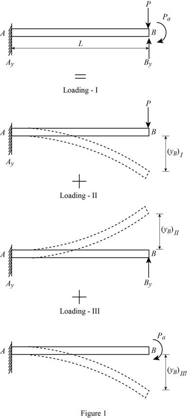
Loading I:
The downward load P is acting at point B of the beam.
Refer to Case 1 in Appendix D “Beam Deflections and Slopes” in the textbook.
Write the deflection equation for concentrated load acting in a cantilever beam as follows;
Find the deflection at point B due to load P at point B as follows;
Loading II:
The upward reaction
Refer to Case 1 in Appendix D “Beam Deflections and Slopes” in the textbook.
Write the deflection equation for concentrated load acting in a cantilever beam as follows;
Find the deflection at point B due to reaction at point B as follows;
Loading III:
The clockwise moment is acting at point B of the beam.
Refer to Case 3 in Appendix D “Beam Deflections and Slopes” in the textbook.
Write the deflection equation for moment in a cantilever beam as follows;
Find the deflection at point B due to the moment at point B as follows;
Find the resultant deflection at point B as follows.
Substitute
Substitute 0.5 mm for
Consider the beam ABC.
Show the free-body diagram of the superimposed beam ABC as in Figure 2.
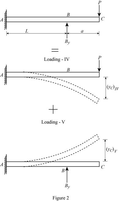
Loading IV:
The downward load P is acting at point C of the beam.
Refer to Case 1 in Appendix D “Beam Deflections and Slopes” in the textbook.
Write the deflection equation for concentrated load acting in a cantilever beam as follows;
Find the deflection at point C due to load P at point C as follows;
Loading V:
The upward reaction
Refer to Case 1 in Appendix D “Beam Deflections and Slopes” in the textbook.
Write the slope and deflection equation for concentrated load acting in a cantilever beam as follows;
Find the deflection at point B due to reaction at point B as follows;
Find the slope at point B due to reaction at point B as follows;
The portion BC remains straight.
Find the deflection at point C due to reaction at point B as follows;
Substitute
Find the resultant deflection at point C as follows.
Substitute
Substitute 1 mm for
Solve the Equation (1) and (2).
Therefore, the magnitude of load P in the beam is
Want to see more full solutions like this?
Chapter 9 Solutions
Connect 1-Semester Access Card for Mechanics of Materials


- A 7/8-in.-diameter rod BC is attached to the lever AB and to the fixed support at C. Lever AB has a uniform cross section 38 in. thick and 1 in. deep. For the loading shown, determine the deflection of point A. Use E=29 *106 psi and G=11.2 *106 psi.arrow_forwardA beam under a uniformly-distributed transverse load is fixed at the end x=0 and roller-supported at the other end x= L. What are the Boundary Conditions needed to completely determine the reactions and thus the deflection curve y(x).arrow_forwardconsider the cantilevered W14 x 30 beam shown E = 29(103) ksi, I = 291 in4 determine the maximum slope of the beam, measured counterclockwise from the positive x axis. determine the maximum deflection of the beam. determine the expression for the elastic curve using the coordinate x for 0 < x < 9 ft, where x is in feet.arrow_forward
- A 4-ft section of aluminum pipe of cross-sectional area 1.75 in2 rests on a fixed support at A. The 58-in.-diameter steel rod BC hangs from a rigid bar that rests on the top of the pipe at B. Knowing that the smodulus of elasticity is 29 3 106 psi for steel and 10.4 3 106 psi for aluminum, determine the deflection of point C when a 15-kip force is applied at C.arrow_forwardThe beam is made of four aluminium plates welded together as shown in Figure 1. Knowing that E = 65 GPa and neglecting the effect of the fillet. i. An engineer has been asked to change the material of the beam from aluminium to bronze, having ultimate normal stress 600 MPa, and E = 100 GPa. The design of the beam will remain as per Figure 1. Determine the maximum bending moment M that can be applied from which the factor of safety will be 2.5.arrow_forwardKnowing that beam AB is an S200 * 34 rolled shape and that P=60 kN, L= 2 m, and E= 200 GPa, determine (a) the slope at A, (b) the deflection at C.arrow_forward
- Using Castigliano’s theorem, determine horizontal and vertical components of deflection at point C. Given: P=1000 N EA= 2*10^6 Narrow_forwardDetermine the absolute maximum bending moment in a 60 ft long simply supported beam due to the series of four moving concentrated loads shown in Fig. P9.14.arrow_forwardFor the simply supported beam carrying the concentrated load P = 276 N at its midspan, determine the magnitude of the maximum slope angle of the beam (in degrees) if d = 2.16 m, E = 12.77 GPa , and I =1681393mm4. NOTE: PLEASE ANSWER IT CORRECTLY. IF YOU ARE NOT SURE ABOUT THE ANSWER, PLEASE SKIP THE QUESTIONPLEASE BOX THE FINAL ANSWER(S)THANK YOU!arrow_forward
- consider the cantilevered W14 x 30 beam shown E = 29(103) ksi, I = 291 in4 determine the expression for the elastic curve using the coordinate x for 0 < x < 9 ft, where x is in feet. v in ft answer in terms of x determine the maximum slope of the beam, measured counterclockwise from the positive x axis. Theta max in rad. determine the maximum deflection of the beam. Vmax in ft.arrow_forwardEach of the links AB and CD is made of aluminum and has a cross-sectional area of 0.2 sq.in. Knowing that they support the rigid member BC, determine the downward deflection (in inches) of point C. if x = 13.7 in, y = 28.1 in, z = 20 in, E = 10754407 psi, and P = 26 kips.arrow_forwardA cable AB of span L and a simple beam A'B' of the same span are subjected to identical vertical loadings as shown. Show that the magnitude of the bending moment at a point C' in the beam is equal to the product T0h, where T0 is the magnitude of the horizontal component of the tension force in the cable and h is the vertical distance between point C and the chord joining the points of support A and B.arrow_forward
 Elements Of ElectromagneticsMechanical EngineeringISBN:9780190698614Author:Sadiku, Matthew N. O.Publisher:Oxford University Press
 Mechanics of Materials (10th Edition)Mechanical EngineeringISBN:9780134319650Author:Russell C. HibbelerPublisher:PEARSON
 Thermodynamics: An Engineering ApproachMechanical EngineeringISBN:9781259822674Author:Yunus A. Cengel Dr., Michael A. BolesPublisher:McGraw-Hill Education
 Control Systems EngineeringMechanical EngineeringISBN:9781118170519Author:Norman S. NisePublisher:WILEY
 Mechanics of Materials (MindTap Course List)Mechanical EngineeringISBN:9781337093347Author:Barry J. Goodno, James M. GerePublisher:Cengage Learning
 Engineering Mechanics: StaticsMechanical EngineeringISBN:9781118807330Author:James L. Meriam, L. G. Kraige, J. N. BoltonPublisher:WILEY