Vector Mechanics for Engineers: Statics, 11th Edition
11th Edition
ISBN: 9780077687304
Author: Ferdinand P. Beer, E. Russell Johnston Jr., David Mazurek
Publisher: McGraw-Hill Education
bartleby

Videos

Question
Book Icon
Chapter 9.5, Problem 9.139P
To determine

Find the mass moment of inertia of the anchor with respect to each of the coordinate axes.

Expert Solution & Answer
Check Mark

Answer to Problem 9.139P

The mass moment of inertia (Ix) of the anchor with respect to x axis is 344×106lbfts2_.

The mass moment of inertia (Iy) of the anchor with respect to y axis is 132.1×10⁶lbfts2_.

The mass moment of inertia (Iz) of the anchor with respect to z axis is 453×106lbfts2_.

Explanation of Solution

Given information:

The thickness (t) of the anchor is 0.05in.

The specific weight (γ) of the galvanized steel is 470lb/ft3.

Assume the acceleration due to gravity (g) as 32.2ft/s2

Calculation:

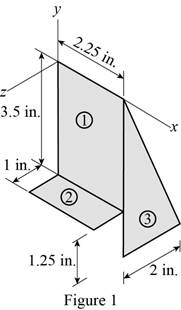
Show the section 1, section 2 and section 3 of the framing anchor as in Figure 1.

Vector Mechanics for Engineers: Statics, 11th Edition, Chapter 9.5, Problem 9.139P

Calculate the density (ρ) of the galvanized steel using the relation:

ρ=γg

Substitute 470lb/ft3 for γ and 32.2ft/s2 for g.

ρ=47032.2=14.596lbs2/ft4

Calculate the volume of the section 1 (V1) using the relation:

V1=A1t=3.5×2.25×t

Substitute 0.05in. for t.

V1=3.5×2.25×0.05=0.39375in.3×(1ft12in.)3=2.2786×104ft3

Calculate the volume of the section 2 (V2) as below:

V2=A2t=1×2.25×t

Substitute 0.05in. for t.

V2=1×2.25×0.05=0.1125in.3×(1ft12in.)3=6.5104×105ft3

Calculate the volume (V3) of the section 3 as below:

V3=A3t=12(3.5+1.25)×2×t

Substitute 0.05in. for t.

V3=12×(3.5+1.25)×2×0.05=0.2375in.3×(1ft12in.)3=1.3744×104ft3

Calculate the mass of section 1 (m1) using the relation:

m1=ρV1

Substitute 2.2786×104ft3 for V1 and 14.596lbs2/ft4 for ρ.

m1=14.596×2.2786×104=3325.845×106lbs2/ft

Calculate the mass of section 2 (m2) using the relation:

m2=ρV2

Substitute 6.5104×105ft3 for V2 and 14.596lbs2/ft4 for ρ.

m2=14.596×6.5104×105=950.26×10⁶lbs2/ft

Calculate the mass of section 3 (m3) using the relation:

m3=ρV3

Substitute 1.3744×104ft3 for V3 and 14.596lbs2/ft4 for ρ.

m3=14.596×1.3744×104=2006.14×106lbs2/ft

Calculate the mass moment of inertia with respect to x axis for section 1 (Ix)1 as below:

(Ix)1=112(m1)(3.5)2+(m1×(3.52)2)

Substitute 3325.845×106lbs2/ft for m1.

(Ix)1=112(3325.845×106lbs2/ft)(3.5in.×1ft12in.)2+(3325.845×106lbs2/ft×((3.5in.)×1ft12in.2)2)=2.3577×105+7.073×105=9.4307×105lbfts2

Calculate the mass moment of inertia with respect to x axis for  section 2 (Ix)2 as below:

(Ix)2=112(m2)(1)2+(m2×(3.52+(12)2))

Substitute 950.26×10⁶lbs2/ft for m2.

(Ix)2=112(950.26×10⁶lbs2/ft)(1in.×1ft12in.)2+(950.26×106lbs2/ft× ((3.5in.×1ft12in.)2+((1in.×1ft12in.)2)2))=5.4992×10⁷+8.2488×105=83.037×10⁶lbfts2

Calculate the mass moment of inertia with respect to x axis for section 3 (Ix)3 as below:

(Ix)3=118(m3)((3.5+1.25)2+22)+(m3×((23(3.5+1.25))2+(13×2)2))

Substitute 2006.14×106lbs2/ft for m3.

(Ix)3=118(2006.14×106lbs2/ft)(((3.5+1.25)in.×1ft12in.)2+(2in.×1ft12in.)2)+ +(2006.14×106lbs2/ft×((23((3.5+1.25)in.×1ft12in.))2+(13×2in.×1ft12in.)2))=2.0558×105+1.4589×104=166.452×106lbfts2

Calculate the mass moment of inertia with respect to x axis for anchor (Ix) using the parallel axis theorem as below:

Ix=(Ix)1+(Ix)2+(Ix)3

Substitute 9.4307×10⁵lbfts2 for (Ix)1, 83.037×10⁶lbfts2 for (Ix)2 and 166.452×10⁶lbfts2 for (Ix)3.

Ix=9.4307×10⁵+83.037×10⁶+166.452×106=3.437×10⁴lbfts2344×106lbfts2

Calculate the mass moment of inertia with respect to y axis for section 1 (Iy)1 as below:

(Iy)1=112m1(2.25)2+m1(2.252)2

Substitute 3325.845×106lbs2/ft for m1.

(Iy)1={112×3325.845×106lbs2/ft×(2.25in.×1ft12in.)2 +3325.845×106lbs2/ft×((2.25in.×1ft12in.)2)2}=9.7436×106+2.923×105=38.975×106lbfts2

Calculate the mass moment of inertia with respect to y axis for section 2 (Iy)2 as below:

(Iy)2=112m2((2.25)2+(1)2)+m2[(2.252)2+(12)2]

Substitute 950.26×10⁶lbs2/ft for m2.

(Iy)2={112(950.26×10⁶lbs2/ft)((2.25in.×1ft12in.)2+(1in.×1ft12in.)2) +950.26×10⁶lbs2/ft[((2.25in.×1ft12in.)2)2+(1in.×1ft12in.2)2]}=3.334×106+1.00017×105=13.336×106lbfts2

Calculate the mass moment of inertia with respect to y axis for section 3 (Iy)3 as below:

(Iy)3=118m3(2)2+m3[2.252+(132)2]

Substitute 2006.14×106lbs2/ft for m3.

(Iy)3={118×2006.14×106lbs2/ft(2in.×1ft12in.)2 +2006.14×106lbs2/ft[(2.25in.×1ft12in.)2+(13×(2in.×1ft12in.))2]}=3.096×106+7.672×105=79.816×106lbfts2

Calculate the mass moment of inertia with respect to y axis for anchor (Iy) using the parallel axis theorem as below:

Iy=(Iy)1+(Iy)2+(Iy)3

Substitute 38.975×10⁶lbfts2 for (Iy)1 13.336×10⁶lbfts2 for (Iy)2 and 79.816×10⁶lbfts2 for (Iy)3.

Iy=38.975×10⁶+13.336×10⁶+79.816×106=132.127×10⁶lbfts2132.1×106lbfts2

Calculate the mass moment of inertia with respect to z axis for section 1 (Iz)1 as below:

(Iz)1=112m1[(2.25)2+(3.5)2]+m1[(2.252)2+(3.52)2]

Substitute 3325.845×106lbs2/ft for m1.

(Iz)1={1123325.845×106lbs2/ft[(2.25in.×1ft12in.)2+(3.5in.×1ft12in.)2] +3325.845×106lbs2/ft[(2.25in.×1ft12in.2)2+(3.5in.×1ft12in.2)2]}=3.332×105+9.996×105=133.283×106lbfts2

Calculate the mass moment of inertia with respect to z axis for section 2 (Ix)2 as below:

(Iz)2=112m2(2.25)2+m2[(2.252)2+(3.5)2]

Substitute 950.26×10⁶lbs2/ft for m2.

(Iz)2={112×950.26×106lbs2/ft×(2.25in.×1ft12in.)2 +950.26×10⁶lbs2/ft×[(2.25in.×1ft12in.2)2+(3.5in.×1ft12in.)2]}=2.784×106+8.918×105=91.974×106lbfts2

Calculate the mass moment of inertia with respect to z axis for section 3 (Iy)3 as below:

(Iz)3=118m3(3.5+1.25)2+m3[(2.25)2+(23(3.5+1.25))2]

Substitute 2006.14×106lbs2/ft for m3.

(Iz)3={118×2006.14×106lbs2/ft((3.5+1.25)in.×1ft12in.)2 +2006.14×106lbs2/ft×[(2.25in.×1ft12in.)2+(23((3.5+1.25)in.×1ft12in.))2]}=1.746×106+2.102×104=227.694×106lbfts2

Calculate the mass moment of inertia with respect to z axis for anchor (Ix) using the parallel axis theorem as below:

Iz=(Iz)1+(Iz)2+(Iz)3

Substitute 133.283×10⁶lbfts2 for (Iz)1 91.974×10⁶lbfts2 for (Iz)2 and 227.694×10⁵lbfts2 for (Iz)3.

Iz=133.283×10⁶+91.974×10⁶+2.27.694×106=452.951×10⁶lbfts2453×106lbfts2

Therefore, the mass moment of inertia (Ix) of the anchor with respect to x axis is 344×106lbfts2_.

Therefore, the mass moment of inertia (Iy) of the anchor with respect to y axis is 132.1×10⁶lbfts2_.

Therefore, the mass moment of inertia (Iz) of the anchor with respect to z axis is 453×106lbfts2_.

Want to see more full solutions like this?

Subscribe now to access step-by-step solutions to millions of textbook problems written by subject matter experts!

Chapter 9 Solutions

Vector Mechanics for Engineers: Statics, 11th Edition

Ch. 9.1 - 9.9 through 9.11 Determine by direct integration...Ch. 9.1 - 9.12 through 9.14 Determine by direct integration...Ch. 9.1 - Prob. 9.13PCh. 9.1 - 9.12 through 9.14 Determine by direct integration...Ch. 9.1 - 9.15 through 9.16 Determine the moment of inertia...Ch. 9.1 - 9.15 through 9.16 Determine the moment of inertia...Ch. 9.1 - 9.17 through 9.18 Determine the moment of inertia...Ch. 9.1 - Prob. 9.18PCh. 9.1 - Prob. 9.19PCh. 9.1 - Prob. 9.20PCh. 9.1 - Prob. 9.21PCh. 9.1 - 9.21 and 9.22 Determine the polar moment of...Ch. 9.1 - 9.23 and 9.24 Determine the polar moment of...Ch. 9.1 - 9.23 and 9.24 Determine the polar moment of...Ch. 9.1 - (a) Determine by direct integration the polar...Ch. 9.1 - (a) Show that the polar radius of gyration kQ of...Ch. 9.1 - Determine the polar moment of inertia and the...Ch. 9.1 - Determine the polar moment of inertia and the...Ch. 9.1 - Using the polar moment of inertia of the isosceles...Ch. 9.1 - Prove that the centroidal polar moment of inertia...Ch. 9.2 - 9.31 and 9.32 Determine the moment of inertia and...Ch. 9.2 - 9.31 and 9.32 Determine the moment of inertia and...Ch. 9.2 - 9.33 and 9.34 Determine the moment of inertia and...Ch. 9.2 - 9.33 and 9.34 Determine the moment of inertia and...Ch. 9.2 - 9.35 and 9.36 Determine the moments of inertia of...Ch. 9.2 - Prob. 9.36PCh. 9.2 - 9.37 The centroidal polar moment of inertia of...Ch. 9.2 - 9.38 Determine the centroidal polar moment of...Ch. 9.2 - 9.39 Determine the shaded area and its moment of...Ch. 9.2 - 9.40 Knowing that the shaded area is equal to 6000...Ch. 9.2 - 9.41 through 9.44 Determine the moments of inertia...Ch. 9.2 - 9.41 through 9.44 Determine the moments of inertia...Ch. 9.2 - 9.41 through 9.44 Determine the moments of inertia...Ch. 9.2 - Prob. 9.44PCh. 9.2 - 9.45 and 9.46 Determine the polar moment of...Ch. 9.2 - 9.45 and 9.46 Determine the polar moment of...Ch. 9.2 - Prob. 9.47PCh. 9.2 - Prob. 9.48PCh. 9.2 - 9.49 Two channels and two plates are used to form...Ch. 9.2 - 9.50 Two . angles are welded together to form the...Ch. 9.2 - Four L3 3 14 - in. angles are welded to a rolled...Ch. 9.2 - Two 20-mm steel plates are welded to a rolled S...Ch. 9.2 - A channel and a plate are welded together as shown...Ch. 9.2 - The strength of the rolled W section shown is...Ch. 9.2 - Two L76 76 6.4-mm angles are welded to a C250 ...Ch. 9.2 - Two steel plates are welded to a rolled W section...Ch. 9.2 - 9.57 and 9.58 The panel shown forms the end of a...Ch. 9.2 - 9.57 and 9.58 The panel shown forms the end of a...Ch. 9.2 - Prob. 9.59PCh. 9.2 - Prob. 9.60PCh. 9.2 - A vertical trapezoidal gate that is used as an...Ch. 9.2 - The cover for a 0.5-m-diameter access hole in a...Ch. 9.2 - Determine the x coordinate of the centroid of the...Ch. 9.2 - Determine the x coordinate of the centroid of the...Ch. 9.2 - Show that the system of hydrostatic forces acting...Ch. 9.2 - Show that the resultant of the hydrostatic forces...Ch. 9.3 - 9.67 through 9.70 Determine by direct integration...Ch. 9.3 - Prob. 9.68PCh. 9.3 - 9.67 through 9.70 Determine by direct integration...Ch. 9.3 - 9.67 through 9.70 Determine by direct integration...Ch. 9.3 - 9.71 through 9.74 Using the parallel-axis theorem,...Ch. 9.3 - 9.71 through 9.74 Using the parallel-axis theorem,...Ch. 9.3 - 9.71 through 9.74 Using the parallel-axis theorem,...Ch. 9.3 - Prob. 9.74PCh. 9.3 - 9.75 through 9.78 Using the parallel-axis theorem,...Ch. 9.3 - 9.75 through 9.78 Using the parallel-axis theorem,...Ch. 9.3 - 9.75 through 9.78 Using the parallel-axis theorem,...Ch. 9.3 - Prob. 9.78PCh. 9.3 - Determine for the quarter ellipse of Prob. 9.67...Ch. 9.3 - Determine the moments of inertia and the product...Ch. 9.3 - Determine the moments of inertia and the product...Ch. 9.3 - 9.75 through 9.78 Using the parallel-axis theorem,...Ch. 9.3 - Determine the moments of inertia and the product...Ch. 9.3 - Determine the moments of inertia and the product...Ch. 9.3 - Prob. 9.85PCh. 9.3 - 9.86 through 9.88 For the area indicated,...Ch. 9.3 - 9.86 through 9.88 For the area indicated,...Ch. 9.3 - 9.86 through 9.88 For the area indicated,...Ch. 9.3 - 9.89 and 9.90 For the angle cross section...Ch. 9.3 - 9.89 and 9.90 For the angle cross section...Ch. 9.4 - Using Mohrs circle, determine for the quarter...Ch. 9.4 - Using Mohrs circle, determine the moments of...Ch. 9.4 - Using Mohrs circle, determine the moments of...Ch. 9.4 - Using Mohrs circle, determine the moments of...Ch. 9.4 - Using Mohrs circle, determine the moments of...Ch. 9.4 - Using Mohrs circle, determine the moments of...Ch. 9.4 - For the quarter ellipse of Prob. 9.67, use Mohrs...Ch. 9.4 - Prob. 9.98PCh. 9.4 - 9.98 though 9.102 Using Mohrs circle, determine...Ch. 9.4 - 9.98 though 9.102 Using Mohrs circle, determine...Ch. 9.4 - 9.98 through 9.102 Using Mohrs circle, determine...Ch. 9.4 - 9.98 through 9.102 Using Mohrs circle, determine...Ch. 9.4 - Prob. 9.103PCh. 9.4 - 9.104 and 9.105 Using Mohrs circle, determine the...Ch. 9.4 - 9.104 and 9.105 Using Mohrs circle, determine the...Ch. 9.4 - Prob. 9.106PCh. 9.4 - it is known that for a given area Iy = 48 106 mm4...Ch. 9.4 - Prob. 9.108PCh. 9.4 - Using Mohrs circle, prove that the expression...Ch. 9.4 - Using the invariance property established in the...Ch. 9.5 - A thin plate with a mass m is cut in the shape of...Ch. 9.5 - A ring with a mass m is cut from a thin uniform...Ch. 9.5 - Prob. 9.113PCh. 9.5 - The parabolic spandrel shown was cut from a thin,...Ch. 9.5 - Prob. 9.115PCh. 9.5 - Fig. P9.115 and P9.116 9.116 A piece of thin,...Ch. 9.5 - Prob. 9.117PCh. 9.5 - Prob. 9.118PCh. 9.5 - Prob. 9.119PCh. 9.5 - The area shown is revolved about the x axis to...Ch. 9.5 - Prob. 9.121PCh. 9.5 - 9.122 Determine by direct integration the mass...Ch. 9.5 - Prob. 9.123PCh. 9.5 - Determine by direct integration the mass moment of...Ch. 9.5 - Prob. 9.125PCh. 9.5 - A thin steel wire is bent into the shape shown....Ch. 9.5 - Shown is the cross section of an idler roller....Ch. 9.5 - Shown is the cross section of a molded flat-belt...Ch. 9.5 - Prob. 9.129PCh. 9.5 - Prob. 9.130PCh. 9.5 - Prob. 9.131PCh. 9.5 - Prob. 9.132PCh. 9.5 - After a period of use, one of the blades of a...Ch. 9.5 - Determine the mass moment of inertia of the 0.9-lb...Ch. 9.5 - 9.135 and 9.136 A 2-mm thick piece of sheet steel...Ch. 9.5 - 9.135 and 9.136 A 2 -mm thick piece of sheet steel...Ch. 9.5 - Prob. 9.137PCh. 9.5 - A section of sheet steel 0.03 in. thick is cut and...Ch. 9.5 - Prob. 9.139PCh. 9.5 - Prob. 9.140PCh. 9.5 - The machine element shown is fabricated from...Ch. 9.5 - Determine the mass moments of inertia and the...Ch. 9.5 - Determine the mass moment of inertia of the steel...Ch. 9.5 - Fig. P9.143 and P9.144 9.144 Determine the mass...Ch. 9.5 - Determine the mass moment of inertia of the steel...Ch. 9.5 - Aluminum wire with a weight per unit length of...Ch. 9.5 - The figure shown is formed of 18-in.-diameter...Ch. 9.5 - A homogeneous wire with a mass per unit length of...Ch. 9.6 - Determine the mass products of inertia Ixy, Iyz,...Ch. 9.6 - Determine the mass products of inertia Ixy, Iyz,...Ch. 9.6 - Prob. 9.151PCh. 9.6 - Determine the mass products of inertia Ixy, Iyz,...Ch. 9.6 - Prob. 9.153PCh. 9.6 - Prob. 9.154PCh. 9.6 - 9.153 through 9.156 A section of sheet steel 2 mm...Ch. 9.6 - 9.153 through 9.156 A section of sheet steel 2 mm...Ch. 9.6 - The figure shown is formed of 1.5-mm-diameter...Ch. 9.6 - Prob. 9.158PCh. 9.6 - 9.159 and 9.160 Brass wire with a weight per unit...Ch. 9.6 - Fig. P9.160 9.159 and 9.160 Brass wire with a...Ch. 9.6 - Complete the derivation of Eqs. (9.47) that...Ch. 9.6 - Prob. 9.162PCh. 9.6 - Prob. 9.163PCh. 9.6 - Prob. 9.164PCh. 9.6 - Shown is the machine element of Prob. 9.141....Ch. 9.6 - Determine the mass moment of inertia of the steel...Ch. 9.6 - The thin, bent plate shown is of uniform density...Ch. 9.6 - A piece of sheet steel with thickness t and...Ch. 9.6 - Determine the mass moment of inertia of the...Ch. 9.6 - 9.170 through 9.172 For the wire figure of the...Ch. 9.6 - Prob. 9.171PCh. 9.6 - 9.172 Prob. 9.146 9.146 Aluminum wire with a...Ch. 9.6 - For the homogeneous circular cylinder shown with...Ch. 9.6 - For the rectangular prism shown, determine the...Ch. 9.6 - Prob. 9.175PCh. 9.6 - Prob. 9.176PCh. 9.6 - Consider a cube with mass m and side a. (a) Show...Ch. 9.6 - Prob. 9.178PCh. 9.6 - Prob. 9.179PCh. 9.6 - 9.180 through 9.184 For the component described in...Ch. 9.6 - 9.180 through 9.184 For the component described in...Ch. 9.6 - Prob. 9.182PCh. 9.6 - 9.180 through 9.184 For the component described in...Ch. 9.6 - 9.180 through 9.184 For the component described in...Ch. 9 - Determine by direct integration the moments of...Ch. 9 - Determine the moment of inertia and the radius of...Ch. 9 - Determine the moment of inertia and the radius of...Ch. 9 - Determine the moments of inertia Ix and Iy of the...Ch. 9 - Determine the polar moment of inertia of the area...Ch. 9 - Two L4 4 12-in. angles are welded to a steel...Ch. 9 - Using the parallel-axis theorem, determine the...Ch. 9 - Prob. 9.192RPCh. 9 - Fig. P9.193 and P9.194 9.193 A thin plate with a...Ch. 9 - Fig. P9.193 and P9.194 9.194 A thin plate with...Ch. 9 - A 2-mm-thick piece of sheet steel is cut and bent...Ch. 9 - Determine the mass moment of inertia of the steel...
Knowledge Booster
Background pattern image
Mechanical Engineering
Learn more about
Need a deep-dive on the concept behind this application? Look no further. Learn more about this topic, mechanical-engineering and related others by exploring similar questions and additional content below.
Recommended textbooks for you
Text book image
Elements Of Electromagnetics
Mechanical Engineering
ISBN:9780190698614
Author:Sadiku, Matthew N. O.
Publisher:Oxford University Press
Text book image
Mechanics of Materials (10th Edition)
Mechanical Engineering
ISBN:9780134319650
Author:Russell C. Hibbeler
Publisher:PEARSON
Text book image
Thermodynamics: An Engineering Approach
Mechanical Engineering
ISBN:9781259822674
Author:Yunus A. Cengel Dr., Michael A. Boles
Publisher:McGraw-Hill Education
Text book image
Control Systems Engineering
Mechanical Engineering
ISBN:9781118170519
Author:Norman S. Nise
Publisher:WILEY
Text book image
Mechanics of Materials (MindTap Course List)
Mechanical Engineering
ISBN:9781337093347
Author:Barry J. Goodno, James M. Gere
Publisher:Cengage Learning
Text book image
Engineering Mechanics: Statics
Mechanical Engineering
ISBN:9781118807330
Author:James L. Meriam, L. G. Kraige, J. N. Bolton
Publisher:WILEY
Differences between Temporary Joining and Permanent Joining.; Author: Academic Gain Tutorials;https://www.youtube.com/watch?v=PTr8QZhgXyg;License: Standard Youtube License