Concept explainers
Videos
Scanning Confocal Microscopy
Although modern microscopes are marvels of optical engineering, their basic design is not too different from the 1665 compound microscope of Robert Hooke. Recently, advances in optics, lasers, and computer technology have made practical a new kind of optical microscope, the scanning confocal microscope. This microscope is capable of taking images of breathtaking clarity.
The figure shows the microscope’s basic principle of operation. The left part of the figure shows how the translucent specimen is illuminated by light from a laser. The laser beam is converted to a diverging bundle of rays by suitable optics, reflected off a mirror, then directed through a microscope objective lens to a focus within the sample. The microscope objective focuses the laser beam to a very small (≈ 0.5 μm) spot. Note that light from the laser passes through other regions of the specimen but, because the rays are not focused in those regions, they are not as intensely illuminated as is the point at the focus. This is the first important aspect of the design: Very intensely illuminate one very small volume of the sample while leaving other regions only weakly illuminated.
As shown in the right half of the figure, light is reflected from all illuminated points in the sample and passes back through the objective lens. The mirror that had reflected the laser light downward is actually a partially transparent
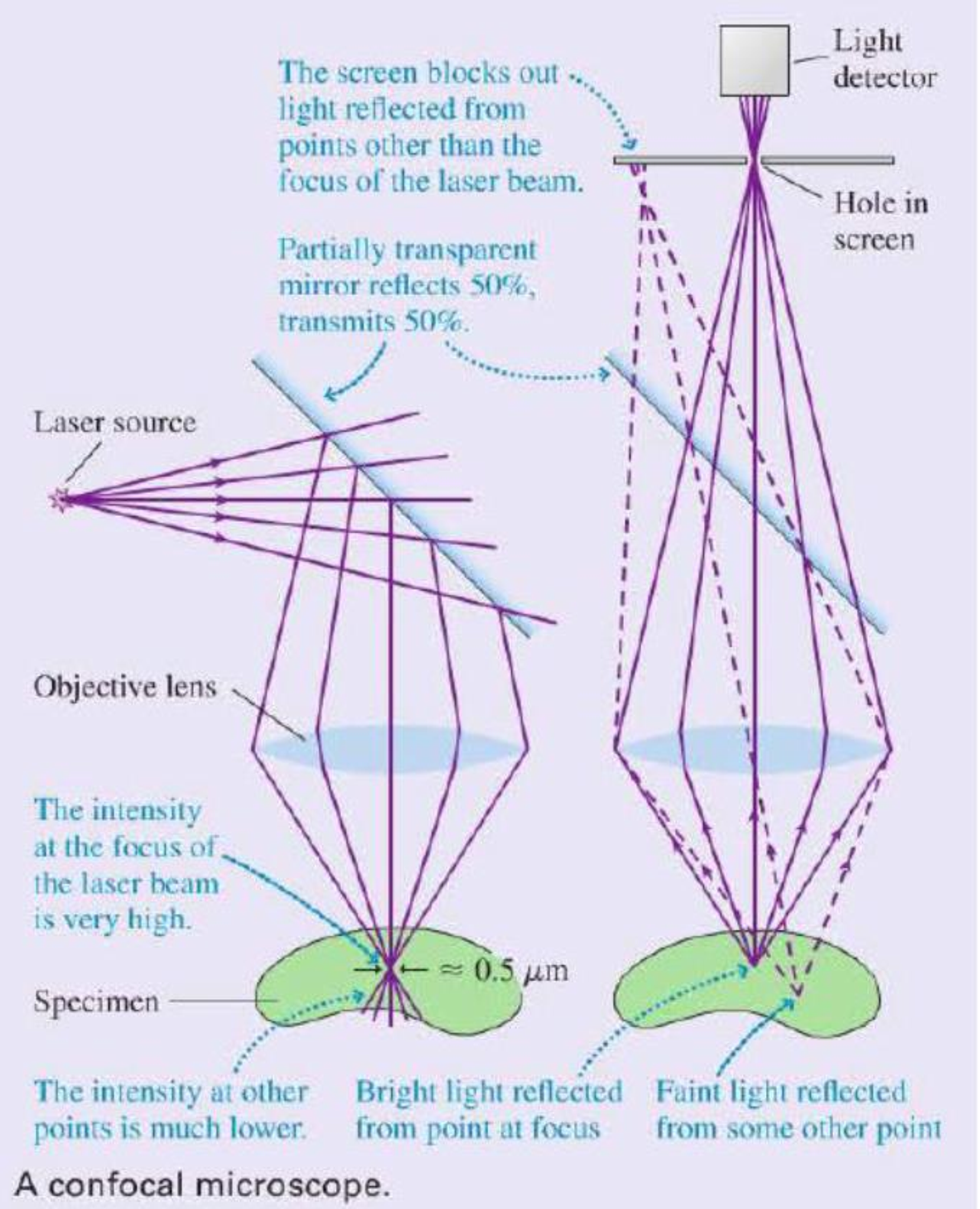
mirror that reflects 50% of the light and transmits 50%. Thus half of the light reflected upward from the sample passes through the mirror and is focused on a screen containing a small hole. Because of the hole, only light rays that emanate from the brightly illuminated volume in the sample can completely pass through the hole and reach the light detector behind it. Rays from other points in the sample either miss the hole completely or are out of locus when they reach the screen, so that only a small fraction of them pass through the hole. This second key design aspect limits the detected light to only those rays that are emitted from the point in the sample at which the laser light was originally focused.
So we see that (a) the point in the sample that is at the focus of the objective is much more intensely illuminated than any other point, so it reflects more rays than any other point, and (b) the hole serves to further limit the detected rays to only those that emanate from the focus. Taken together, these design aspects ensure the detected light comes from a very small, very well-defined volume in the sample.
The microscope as shown would only be useful for examining one small point in the sample. To make an actual image, the objective is scanned across the sample while the intensity is recorded by a computer. This procedure builds up an image of the sample one scan line at a time. The final result is a picture of the sample in the very narrow plane in which the laser beam is focused. Different planes within the sample can be imaged by moving the objective up or down before scanning. It is actually possible to make three dimensional images of a specimen in this way.
The improvement in contrast and resolution over conventional microscopy can be striking. The images show a section of a mouse kidney taken using conventional and confocal microscopy. Because light reflected from all parts of the specimen reaches the camera in a conventional microscope, that image appears blurred and has low contrast. The confocal microscope image represents a single plane or slice of the sample, and many details become apparent that are invisible in the conventional image.

A section of fluorescently stained mouse kidney imaged using standard optical microscopy (left) and scanning confocal microscopy (right).
The following questions are related to the passage “Scanning Con focal Microscopy” on the previous page.
1. A laser beam consists of parallel rays of light. To convert this light to the diverging rays required for a scanning confocal microscope requires
- A. A converging lens.
- B. A diverging lens.
- C. Either a converging or a diverging lens.
Want to see the full answer?
Check out a sample textbook solution
Chapter P Solutions
College Physics: A Strategic Approach (4th Edition)
Additional Science Textbook Solutions
Life in the Universe (4th Edition)
Conceptual Physics (12th Edition)
Cosmic Perspective Fundamentals
Physics for Scientists and Engineers: A Strategic Approach, Vol. 1 (Chs 1-21) (4th Edition)
Conceptual Physical Science (6th Edition)
Physics for Scientists and Engineers with Modern Physics


- An object is placed in front of a converging lens at an object distance of twice the focal length of the lens. Sketch a ray diagram and compare the image and object distances. Repeat with two more ray diagrams, using different focal lengths and still making the object distance twice the focal length. Can you draw any conclusions by comparing the object distance and the image distance?arrow_forwardExplain why a person’s legs appear very short when wading in a pool. Justify your explanation with a ray diagram showing the path of rays from the feet to the eye of an observer who is out of the water.arrow_forwardUnreasonable Results Your friends show you an image through a microscope. They tell you that the microscope has an objective with a 0.500-cm focal length and an eyepiece with a 5.00-cm focal length. The resulting overall magnification is 250,000. Are these viable values for a microscope? Unless otherwise stated, the lens-to-retina distance is 2.00 cm.arrow_forward
- Draw rays to scale to locate the image at the retina if the eye lens has a focal length 2.5 cm and the near point is 24 cm. (Hint: Place an object at the near point.)arrow_forwardAn object is placed to the left of a concave lens with focal length -10 cm such that the image produced by the lens is exactly half the size of the object. In a neat and organized fashion, write out a solution which includes the following: A sketch of the physical situation with all given physical quantities clearly labeled. Draw a ray diagram showing the object, the lens, and the image. Determine the location of the object and the image. Clearly show all steps, starting from generalized equations. Explain your mathematical work in words. Your explanation should cover both what you did and the thought process behind why you did that. Evaluate your answer to determine whether it is reasonable or not. Consider all aspects of your answer (the numerical value, sign, and units) in your evaluation. Please answer 1 and 2 only and thanksarrow_forwardAn object is placed to the left of a concave lens with focal length -10 cm such that the image produced by the lens is exactly half the size of the object. In a neat and organized fashion, write out a solution which includes the following: A sketch of the physical situation with all given physical quantities clearly labeled. Draw a ray diagram showing the object, the lens, and the image. Determine the location of the object and the image. Clearly show all steps, starting from generalized equations. Explain your mathematical work in words. Your explanation should cover both what you did and the thought process behind why you did that. Evaluate your answer to determine whether it is reasonable or not. Consider all aspects of your answer (the numerical value, sign, and units) in your evaluation. Answer all questions from 1-4 In 1 make sure the physical situation is sketch and label In 2 make sure the ray diagram is draw In 4 why the answer is reasonablearrow_forward
- A magnifying glass makes objects look bigger. Describe how a magnifying glass works. Where is the object? Where is the image? Is the image upright or inverted? Real or virtual? Briefly explain your answers in terms of what you know about lenses and ray tracing.arrow_forwardA nature photographer taking a close-up shot of an insect replaces the standard lens on his camera with a lens that has a shorter focal length and is positioned farther from the CCD detector. Explain why he does this.arrow_forwardA microscope with a 6.0 ×× objective lens images a 1.1 mmmm diameter specimen. What is the diameter of the real image of this specimen formed by the objective lens? Express your answer with the appropriate units.arrow_forward
- Ray Diagrams - Diverging Lens A certain diverging lens has a focal length of 58.0 cm. If the object is 44 cm high and is situated 93 cm in front of the diverging lens, determine the following using the mirror and magnification equations: (a) Image distance (b) Magnification of the image (c) Is the image real or virtual, upright or inverted, larger or smaller. (d) Draw the Ray Diagramarrow_forwardThe Lens Equation If F is the focal length of a convex lensand an object is placed at a distance x from the lens, then itsimage will be at a distance y from the lens, where F, x, and yare related by the lens equation1F 1x 1ySuppose that a lens has a focal length of 4.8 cm and that theimage of an object is 4 cm closer to the lens than the objectitself. How far from the lens is the object?arrow_forwardA telephoto lens—designed to produce large images of distant objects—sticks out quite far from the front of the camera. Explain why this is so.arrow_forward
 Physics for Scientists and Engineers: Foundations...PhysicsISBN:9781133939146Author:Katz, Debora M.Publisher:Cengage Learning
 An Introduction to Physical SciencePhysicsISBN:9781305079137Author:James Shipman, Jerry D. Wilson, Charles A. Higgins, Omar TorresPublisher:Cengage Learning
 University Physics Volume 3PhysicsISBN:9781938168185Author:William Moebs, Jeff SannyPublisher:OpenStax
 Glencoe Physics: Principles and Problems, Student...PhysicsISBN:9780078807213Author:Paul W. ZitzewitzPublisher:Glencoe/McGraw-Hill