
Electric Motor Control
10th Edition
ISBN: 9781133702818
Author: Herman
Publisher: CENGAGE L
expand_more
expand_more
format_list_bulleted
Related questions
Question
Show all the steps in detail
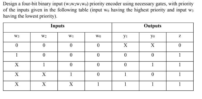

Transcribed Image Text:Design a four-bit binary input (W3W2W1W0) priority encoder using necessary gates, with priority
of the inputs given in the following table (input wo having the highest priority and input w3
having the lowest priority).
Inputs
Outputs
W3
W2
W1
Wo
ут
yo
Ꮓ
0
0
0
0
X
X
0
1
0
0
0
0
0
1
X
1
0
0
0
1
1
X
X
1
0
1
0
X
X
X
1
1
1
1
Expert Solution
This question has been solved!
Explore an expertly crafted, step-by-step solution for a thorough understanding of key concepts.

Step by stepSolved in 2 steps with 2 images

Knowledge Booster

Similar questions
- Create a complete analysis table for the circuit by finding the logic leveis present at each gate output for each of the 16 possible input combinations.arrow_forwardDesign a combinational circuit that takes 3-bit pattern as input and outputs binary code of bit position of the first 1' in the pattern reading from MSB (2nd position) to LSB (0th position).An additional output variable V is required along with binary code to indicate that the binary code is valid or note i.e., if the input pattern is '000' then the output V should be '0' to indicate that the binary code is not indicating the bit position of first 1' and we don't care about the binary code if V = 0. Design the required circuit using dual 4x1 MUXS and minimum additional logic.Available resources along with dual 4x1 MUXS are NOT gates, 2-input(AND, OR, NAND, NOR) gates.arrow_forwardI need solution details in 30 minutesarrow_forward
- How to build this circuit? (on Digital or Logisim) Binary-coded decimal is an alternative method of representing integers using binary. In it, each base-10 digit is represented by four bits, thus each nibble takes one of 10 values (0000 through 1001). Therefore, using BCD, 42 (decimal) is represented as 0100 0010 (binary) and 196 (decimal) is represented as 0001 1001 0110 (binary). Create a circuit in Logisim that accepts as input a pair of two-digit integers represented as BCD and outputs their sum in BCD. Any and all Digital components are fair game. You can assume that all inputs will be valid BCD-encoded numbers.arrow_forwardThe waveforms in Figure 08 are applied to the 4-bit parity logic. Determine the output wave-form in proper relation to the inputs. For how many bit times does even parity occur, and how is it indicated? The timing diagram includes eight bit times. Q.21 Bit time Ao A1 A2 A3 FIGURE 08arrow_forwardIntroduction to Logic design EENG115. Please solve it by introduction to Logic design onley and make your Line clear and step by step pleasearrow_forward
- Give all gates outputarrow_forwardnot use ai please don'tarrow_forwardBelow is a 4-bit up-counter. What is the largest number of the counter if the initial state Q 3 Q 2 Q1Q0 =0011? (D 3 an Q 3 are MSB, and when Load = 1 and Count =1 the counter is loaded with the value D 3 ...D0) 4-bit counter Clock Q3 Load Count "I" or Vcc "I" or Vcc Do "1" or Vcc - D, Qi Q2 "0" or Gnd - D2 "0" or Gnd D3 Q3 1111 0011 1100 0110arrow_forward
arrow_back_ios
SEE MORE QUESTIONS
arrow_forward_ios
Recommended textbooks for you