
Concept explainers
Videos
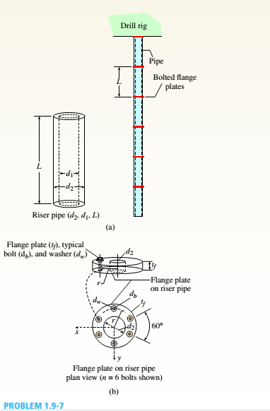
A steel riser pipe hangs from a drill rig. Individual segments of equal length L = 50 ft are joined to get her using bolted flange plates (see figure part b). There are six bolts at each pipe segment connection. The outer and inner pipe diameters are t2= 14 in. and d1= 13 in.; flange plate thickness tf= 1.5 in.; and boll and washer diameters are db= 1.125 in. and dn. = 1.875 in. Find the number n of permissible segments of pipe based on following allowable stresses.
(a) The allowable tensile stress in the pipe is 50 ksi.
(b) The allowable tensile stress in a bolt is 120 ksi. Find number of segments n for two cases: pipe hanging in air and pipe hanging in seawater.
Want to see the full answer?
Check out a sample textbook solution
Chapter 1 Solutions
Bundle: Mechanics Of Materials, Loose-leaf Version, 9th + Mindtap Engineering, 1 Term (6 Months) Printed Access Card


- A large precast concrete panel for a warehouse is raised using two sets of cables at two lift lines, as shown in the figure part a. Cable 1 has a length L1 = 22 Ft, cable 2 has a length L2= 10 ft, and the distance along the panel between lift points Band D is d = 14 ft (see figure part b). The total weight of the panel is W = 85 kips. Assuming the cable lift Forces F at each lift line are about equal, use the simplified model of one half of the panel in figure part b to perform your analysis for the lift position shown. Find the required cross-sectional area AC of the cable if its breaking stress is 91 ksi and a factor of safety of 4 with respect to failure is desired.arrow_forwardTwo pipes {L, = 2.5 m and L, = 1.5 m) are joined al B by flange plales (thickness (, = 14 mm) with five bolts [dlt, = 13 mm] arranged in a circular pal tor n (see figure). Also, each pipe segment is atlaehed to a wall (at .1 and ( '. see figure! using a base plate Uh = 15 mm) and four bolts (dM, = 16 mm). All bolts are tightened until just snug. Assume £, = 110 GPa,E2 = 73 GPa,», = 0.33,andv, = 0.25. Neglect the self-weight of the pipes, and assume the pipes are in a stress-free stale initially. The cross-sectional areas of the pipes are At = 1500 mm: and A2 = (3/5)4. The ollter diameter of Pipe 1 is 60 mm. The outer diameter of Pipe 2 is equal to the inner diameter of Pipe 1. The bolt radius r = 64 mm for both base and flange plates. (a) If torque '/'is applied at .v = Lt. find an expression for reactive torques Iit and IL in terms of T. (b) Find the maximum load variable /'(i.e., Tmal) if allowable torsional stress in the two pipes is Tall0* = 65 MPa-id Draw torsional moment iTMD i and torsional displacement (TDD) diagrams. Label all key ordinales. What is '/>.ll('.' (d) Find mail, if allowable shear and bearing stresses in the base plate and flange bolts cannot be exceeded. Assume allowable stresses in shear an.: :vari:'.g I all bolls are r |Nill, = 45 MPa andtr MaK =90 MPa. (e) Remove torque Tat x — L,. Now assume the flange-plate bolt holes are misaligned by some angle ß (see figure). Find the expressions for reactive torques Rx and R2 if the pipes are twisted to align the flange-plate bolt holes, bolts are then inserted, and the pipes released. (f) What is the maximum permissible misalignment angle ß mix if allowable stresses in shear and bearing for all bolts [from part (d)] are not to be exceeded?arrow_forwardA plane truss has joint loads P, 2P, and 3P at joints D. C, and B. respectively (see figure) where load variable P — 5200 lb. All members have two end plates (see figure For Prob. 1.8-2) that are pin-connected to gusset plates. Each end plate has a thickness/ — 0.6.2.5 in., and all gusset plates have a thickness tg= 1.125 in. IT the allowable shear stress in each pin is 12,000 psi and the allowable bearing stress in each pin is 18.000 psi, what is the minimum required diameter dminof the pins used at either end of member BE1arrow_forward
- A square steel tube of a length L = 20 ft and width b2= 10.0 in. is hoisted by a crane (see figure). The lube hangs from a pin of diameter d that is held by the cables at points A and B. The cross section is a hollow square with an inner dimension b1= 8.5 in. and outer dimension b2= 10,0 in. The allowable shear stress in the pin is 8,700 psi. and the allowable bearing stress between the pin and the tube is 13,000 psi. Determine the minimum diameter of the pin in order to support the weight of the tube. Note: Disregard the rounded corners of the tube when calculating its weight.arrow_forwardA cable and pulley system at D is used to bring a 230-lcg pole (ACB) to a vertical position, as shown in the Figure part a. The cable has tensile force T and is attached at C. The length L of the pole is 6.0m, the outer diameter is d = 140 mm. and the wall thickness is t = 12 mm. The pole pivots about a pin at A in figure part b. The allowable shear stress in the pin is 60 MPa and the allowable bearing stress is 90 MPa. Find the minimum diameter of the pin at A in order to support the weight of the pole in the position shown in the figure part a.arrow_forwardA prospector uses a hand-powered winch (see figure) to raise a bucket of ore in his mine shaft. The axle of the winch is a steel rod of diameter d = 0.625 in. Also, the distance from the center of the axle to the center of the lifting rope is b = 4.0 in, If the weight of the loaded bucket is W = 100 lb, what is the maximum shear stress in the axle due to torsion? If the maximum bucket load is 125 lb and the allowable shear stress in the axle is 9250 psi, what is the minimum permissible axle diameter?arrow_forward
- An inflatable structure used by a traveling circus has the shape of a half-circular cylinder with closed ends (see figure). The fabric and plastic structure is inflated by a small blower and has a radius of 40 ft when fully inflated. A longitudinal scam runs the entire length of the "ridge" of the structure. If the longitudinal scam along the ridge tears open when it is subjected to a tensile load of 540 pounds per inch of seam, what is the factor of safety n against tearing when the internal pressure is 0,5 psi and the structure is fully inflated?arrow_forwardA flanged wooden shape is used to support the loads shown on the beam. The dimensions of the shape are shown in the second figure. Assume LAB = 7 ft, LBc = 3 ft, LCD= 3 ft, LDE = 2 ft, Pc= 2090 lb, PE = 1780 lb, WAB=710 lb/ft, b₁ = 10 in., b₂= 2 in., b3 = 7 in., d₂ = 2 in., d₂ = 7 in., d3=2 in. Consider the entire 15-ft length of the beam and determine: (a) the maximum tension bending stress o at any location along the beam, and (b) the maximum compression bending stress at any location along the beam. Answers: (a) OT: = (b) a = = WAB LAB 1018.59 829.57 B Pc LBC b₁ b3 C LCD psi. psi, D d₁ LDE d₂ d3 PE Earrow_forwardA flanged wooden shape is used to support the loads shown on the beam. The dimensions of the shape are shown in the second figure. Assume LAB = 7 ft. LBC= 2 ft, LCD= 4 ft,LDE = 3 ft, Pc= 1720 lb, Pe=2360 lb, WAB=850 lb/ft, b₂ = 8 in., b₂ = 2 in., b3 = 4 in., d₁ = 2 in., d₂ = 12 in., d3= 2 in. Consider the entire 16-ft length of the beam and determine: (a) the maximum tension bending stress or at any location along the beam, and (b) the maximum compression bending stress ocat any location along the beam. Answers: (a) OT (b) oc= i = i WAB LAB B Pc LBC b₁ b3 C LCD ·b₂ OD psi. psi. d₁ d3 LDE PE Earrow_forward
- A flanged wooden shape is used to support the loads shown on the beam. The dimensions of the shape are shown in the second figure. Assume LAB = 7 ft, LBc= 2 ft, LcD = 3 ft, LDE = 4 ft, Pc= 1760 Ib, PE= 1620 lb, wAB = 830 lb/ft, b1 = 6 in., b2= 2 in., b3= 4 in., d1= 2 in., d2 = 7 in., d3= 2 in. Consider the entire 16-ft length of the beam and determine: (a) the maximum tension bending stress or at any location along the beam, and (b) the maximum compression bending stress oc at any location along the beam. Pc PE WAB B |C LAB LBC LCD LDE b1 di |dz - b2 dz bzarrow_forwardA flanged wooden shape is used to support the loads shown on the beam. The dimensions of the shape are shown in the second figure. Assume LAB = 8 ft. LBc=2 ft, LCD= 4 ft, LDE= 4 ft, Pc = 1850 lb, PE = 2160 lb, WAB = 830 lb/ft, b₁ = 10 in., b2= 2 in., b3 = 6 in., d₁ = 2 in., d₂= 11 in., d3 = 2 in. Consider the entire 18-ft length of the beam and determine: (a) the maximum tension bending stress or at any location along the beam, and (b) the maximum compression bending stress oc at any location along the beam. Answers: (a) σT = (b) a = WAB LAB i 545.779 706.391 B Pc LBC b₁ b3 C LCD -b₂ psi. psi. D ↓ d₁ LDE d₂ PE Earrow_forwardA flanged wooden shape is used to support the loads shown on the beam. The dimensions of the shape are shown in the second figure. Assume LAB = 8 ft. LBc = 2 ft, LCD = 4 ft, LDE = 4 ft, PC= 1850 lb, PE = 2160 lb, WAB = 830 lb/ft, b₁ = 10 in., b₂ = 2 in., b3 = 6 in., d₁= 2 in., d₂ = 11 in., d3 = 2 in. Consider the entire 18-ft length of the beam and determine: (a) the maximum tension bending stress or at any location along the beam, and (b) the maximum compression bending stress oc at any location along the beam. Answers: (a) σT = (b) a = i WAB LAB 666.41 864.39 B Pc 1 LBC b₁ b3 C LCD -b₂ psi. psi. D d₁ d3 LDE PE E Xarrow_forward
 Mechanics of Materials (MindTap Course List)Mechanical EngineeringISBN:9781337093347Author:Barry J. Goodno, James M. GerePublisher:Cengage Learning