
Concept explainers
Videos
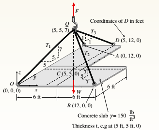
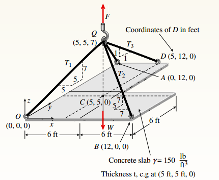
An L-shaped reinforced concrete slab 12 Ft X 12 ft, with a 6 Ft X 6 ft cut-out and thickness t = 9.0 in, is lifted by three cables attached at O, B, and D, as shown in the figure. The cables are are combined at point Q, which is 7.0 Ft above the top of the slab and directly above the center of mass at C. Each cable has an effective cross-sectional area of Ae= 0.12 in2.
(a) Find the tensile force Tr(i = 1, 2, 3) in each cable due to the weight W of the concrete slab
(ignore weight of cables).
(b) Find the average stress ov in each cable. (See Table I-1 in Appendix I for the weight density of reinforced concrete.)
(c) Add cable AQ so that OQA is one continuous cable, with each segment having Force T, which is connected to cables BQ and DQ at point Q. Repeat parts (a) and (b). Hini: There are now three Forced equilibrium equations and one constrain equation, T1= T4.
(a)
Tensile force T in each cable due to weight.
Answer to Problem 1.4.13P
Tensile force T is:
Explanation of Solution
Given Information:
You have the following figure with all relevant information:

Thickness (t) is 9 in.
Calculation:
Consider the free body diagram as:
To calculate external reaction force F, take equilibrium of forces as:
The following force acts on point Q:
Take equilibrium of forces at Q as:
Solve the above equation to get:
Conclusion:
Therefore, the correct answers are
(b)
Average stress in each cable.
Answer to Problem 1.4.13P
Stress in each cable is
Explanation of Solution
Given Information:
You have following figure with all relevant information:

Thickness (t) is 9 in. and cross-sectional area of each cable is
Calculation:
Consider the free body diagram as,

To calculate external reaction force F, take equilibrium of forces as,
The following forces acts on point Q:
Take equilibrium of forces at Q as:
Solve the above equation to get,
Calculate stress as,
Conclusion:
Therefore, the correct answer is:
(c)
Tensile force and average stress in each cable.
Answer to Problem 1.4.13P
Stress in each cable is:
Explanation of Solution
Given Information:
You have following figure with all relevant information:

Thickness (t) is 9 in. and cross-sectional area of each cable is
Calculation:
Consider the free body diagram as,

To calculate external reaction force F, take equilibrium of forces as:
The following force acts on point Q:
Take equilibrium of force at Q as:
Solve the above equation along with
Calculate stress as:
Conclusion:
Therefore, the correct answers are:
Want to see more full solutions like this?
Chapter 1 Solutions
Bundle: Mechanics Of Materials, Loose-leaf Version, 9th + Mindtap Engineering, 1 Term (6 Months) Printed Access Card


- A large precast concrete panel for a warehouse is raised using two sets of cables at two lift lines, as shown in the figure part a. Cable 1 has a length L1 = 22 Ft, cable 2 has a length L2= 10 ft, and the distance along the panel between lift points Band D is d = 14 ft (see figure part b). The total weight of the panel is W = 85 kips. Assuming the cable lift Forces F at each lift line are about equal, use the simplified model of one half of the panel in figure part b to perform your analysis for the lift position shown. Find the required cross-sectional area AC of the cable if its breaking stress is 91 ksi and a factor of safety of 4 with respect to failure is desired.arrow_forwardA long re Lai nine: wall is braced by wood shores set at an angle of 30° and supported by concrete thrust blocks, as shown in the first part of the figure. The shores are evenly spaced at 3 m apart. For analysis purposes, the wall and shores are idealized as shown in the second part of the figure. Note that the base of the wall and both ends of the shores are assumed to be pinned. The pressure of the soil against the wall is assumed to be triangularly distributed, and the resultant force acting on a 3-meter length of the walls is F = 190 kN. If each shore has a 150 mm X 150 mm square cross section, what is the compressive stressarrow_forwardA cylindrical brick chimney of height H weighs w = 825 lb/ft of height (see figure). The inner and outer diameters are d1= 3 ft and d2= 4 ft, respectively. The wind pressure against the side of the chimney is p = 10 lb/ft2 of projected area. Determine the maximum height H if there is to be no tension in the brickwork.arrow_forward
- A long, slender bar in the shape of a right circular cone with length L and base diameter d hangs vertically under the action of its own weight (see figure). The weight of the cone is W and the modulus of elasticity of the material is E. Derive a formula for the increase S in the length of the bar due to its own weight. (Assume that the angle of taper of the cone is small.)arrow_forwardThe roof over a concourse at an airport is supported by the use of pretensioned cables. At a typical joint in the roof structure, a strut AB is compressed by the action of tensile forces Fin a cable that makes an angle = 75° with the strut (see figure and photo). The strut is a circular tube of steel (E = 30,000 ksi) with outer diameter d2= 2.5 in. and inner diameter d1= 2.0 in. The strut is 5.75 ft long and is assumed to be pin-connected at both ends. Using a factor of safety n = 2.5 with respect to the critical load, determine the allowable force F in the cable.arrow_forwardThe main cables of a suspension bridge (see figure part a) follow a curve that is nearly parabolic because the primary load on the cables is the weight of the bridge deck, which is uniform in intensity along the horizontal. Therefore, represent the central region AOB of one of the main cables (see part b of the figure) as a parabolic cable supported at points A and B and carrying a uniform load of intensity q along the horizontal. The span of the cable is L, the sag is /i, the axial rigidity is EA\ and the origin of coordinates is at mid span. (a) Derive the following formula for the elongation of cable AOB shown in part b or the figure: (b) Calculate the elongation 5 of the central span of one of the main cables of the Golden Gate Bridge for which the dimensions and properties are L = 4200 ft,h = 470 ft, q = 12,700 lb/ft, and E = 23,300,000 psi The cable consists of 27,572 parallel wires of diameter 0.196 in. Hint: Determine the tensile force Tal any point in the cable from a free-body diagram of part of the cable; then determine the elongation of an element of the cable of length ds: finally, integrate along the curve of the cable to obtain an equation for the elongation £.arrow_forward
- Problem 3 The boom AB supports a load of W = 720 lb. The boom is supported by a ball-and-socket joint at A and by two cables, BC and BD. Find the tension in each cable and the axial force in the boom, assuming that point C is 4 inches vertically above the position shown in the figure and the other dimensions are unchanged. Neglect the weight of the boom. -9 in.- 8 in. B 12 in. W = 720 lb %3Darrow_forwardExample: Body M shown in figure weighs (300 N) and the homogeneous bar BE weighs (60 N). Draw the free body diagram of each of the two bodies cable smooth C surface 30° MNarrow_forwardThe triangular block shown in the figure is subjected to the loads P = 1600 lb. and F = 600 lb. If AB = 8 in and BC = 6 in., resolve each load into components normal and tangential to AC.arrow_forward
- A 5.15-N beam of uniform density is 1.70 m long. The beam is supported at an angle of 35.0° by a cable attached to one end. There is a pin through the other end of the beam (see figure below). Use the values given in the figure to find the tension in the cable. (Assume L = 1.70 m and d = 0.390 m.) Note: The answer is 2.51 N per the text. I would just like someone to help/show me how to get there. Thank you.arrow_forwardProblem 1: The T-shaped arm ABC shown in the figure lies in a vertical plane and pivots about a horizontal pin at A. The arm has constant cross-sectional area and total weight W. A vertical spring of stiffness k supports the arm at point B. Obtain a formula for the elongation of the spring due to the weight of the arm. Carrow_forwardAxial loads are applied to the solid cylindrical rods as shown. The loads P = 1500 lb, Q = 900, and R = 1300 lb. Find the maximum internal normal force in the structure. (A) - 2300 lb R (B) - 1500 lb (1) (2) (3) (C) - 1300 lb R (D) - 300 lb (E) O lb (F) 300 lb (G) 1300 lb (H) 1500 lb (1) 2300 lb (J) None of the abovearrow_forward
 Mechanics of Materials (MindTap Course List)Mechanical EngineeringISBN:9781337093347Author:Barry J. Goodno, James M. GerePublisher:Cengage Learning