A long re Lai nine: wall is braced by wood shores set at an angle of 30° and supported by concrete thrust blocks, as shown in the first part of the figure. The shores are evenly spaced at 3 m apart. For analysis purposes, the wall and shores are idealized as shown in the second part of the figure. Note that the base of the wall and both ends of the shores are assumed to be pinned. The pressure of the soil against the wall is assumed to be triangularly distributed, and the resultant force acting on a 3-meter length of the walls is F = 190 kN. If each shore has a 150 mm X 150 mm square cross section, what is the compressive stress & i in the shores?
A long re Lai nine: wall is braced by wood shores set at an angle of 30° and supported by concrete thrust blocks, as shown in the first part of the figure. The shores are evenly spaced at 3 m apart. For analysis purposes, the wall and shores are idealized as shown in the second part of the figure. Note that the base of the wall and both ends of the shores are assumed to be pinned. The pressure of the soil against the wall is assumed to be triangularly distributed, and the resultant force acting on a 3-meter length of the walls is F = 190 kN. If each shore has a 150 mm X 150 mm square cross section, what is the compressive stress & i in the shores?
A long re Lai nine: wall is braced by wood shores set at an angle of 30° and supported by concrete thrust blocks, as shown in the first part of the figure. The shores are evenly spaced at 3 m apart. For analysis purposes, the wall and shores are idealized as shown in the second part of the figure. Note that the base of the wall and both ends of the shores are assumed to be pinned. The pressure of the soil against the wall is assumed to be triangularly distributed, and the resultant force acting on a 3-meter length of the walls is F = 190 kN.
If each shore has a 150 mm X 150 mm square cross section, what is the compressive stress &iin the shores?
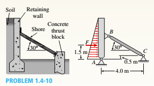
A long retaining wall is braced by wood shores set at an angle of 308 and supported by concrete thrust blocks, as shown in the first part of thefigure. The shores are evenly spaced at 3 m apart. For analysis purposes, the wall and shores are idealized as shown in the second part of the figure.Note that the base of the wall and both ends of the shores are assumed to be pinned. The pressure of the soil against the wall is assumed to be triangularly distributed, and the resultant force acting on a 3-meter length of the walls is F =190 kN. If each shore has a 150 mm 3150 mm square cross section, what is the compressive stress σc in the shores?
A new art exhibit featuring mobile works is going up in the Norwalk, CA area. One art work is shown in the
figure below. A 105 N uniform beam is pinned to the ground by a pivot. The beam is supported by a cable
(attached 3/5 from the bottom of the beam) to allow for each of the shoes to hang freely. Each individual
shoe has a weight of 7.5 N.
10
WALL
FLOR
(a) ( If one shoe is attached 1/7 of the way up the beam and another shoe is attached 5/8 of the way up
the beam, with e, = 70.1° and e, 30.1°, what is the tension in the cable, in newtons?
%3!
%3D
(b)
What is the x-component of the force, in newtons, that the pivot exerts on the bottom of the beam?
(c) O What is the y-component of the force, in newtons, that the pivot exerts on the bottom of the beam?
A new art exhibit featuring mobile works is going up in the Holland, MI, area. One piece is shown in the figure. The 155-N uniform beam is pinned to the ground by a pivot. The beam is supported by a cable (attached to the center of the beam) to allow for each of the shoes to hang freely. Each individual shoe has a weight of 9.5-N.
If one shoe is attached two-fifths of the way up the beam and another shoe is attached and three-fifths of the way up the beam, with θc = 16.5° and θb = 33.6° as shown in the figure, what is the tension in the cable, in newtons?
What is the x-component of the force, in newtons, that the pivot exerts on the bottom of the beam? Use the coordinate system specified in the figure.
What is the y-component of the force, in newtons, that the hinge exerts on the bottom of the beam? Use the coordinate system specified in the figure.
Chapter 1 Solutions
Bundle: Mechanics Of Materials, Loose-leaf Version, 9th + Mindtap Engineering, 1 Term (6 Months) Printed Access Card
Need a deep-dive on the concept behind this application? Look no further. Learn more about this topic, mechanical-engineering and related others by exploring similar questions and additional content below.


 Mechanics of Materials (MindTap Course List)Mechanical EngineeringISBN:9781337093347Author:Barry J. Goodno, James M. GerePublisher:Cengage Learning