SYSTEM DYNAMICS LL+CONNECT
3rd Edition
ISBN: 9781264201891
Author: Palm
Publisher: MCG CUSTOM
bartleby

Videos

Question
Book Icon
Chapter 10, Problem 10.28P
To determine

The steady-state error due to a unit-ramp command and due to a unit-ramp disturbance of I controller with an internal feedback loop of first order plant for the given cases.

Expert Solution & Answer
Check Mark

Answer to Problem 10.28P

The steady-state error values for all the cases are:

Case 1. For ζ=0.707 ,

Error due to unit-ramp command: ess=0.2

Error due to unit-ramp disturbance: ess=0.005

Case 2. For ζ=1 ,

Error due to unit-ramp command: ess=0.4

Error due to unit-ramp disturbance: ess=0.01

Case 3. For a root separation factor of 10,

Error due to unit-ramp command: ess=0.22

Error due to unit-ramp disturbance: ess=0.001.

Explanation of Solution

Given:

The I controller with an internal feedback loop of first order plant is as shown below:

SYSTEM DYNAMICS LL+CONNECT, Chapter 10, Problem 10.28P

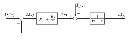
Where, the parameter values are as given:

I=c=4

Also, the performance specifications require the time constant of the system to be τ=0.2.

The values of gains for the I controller are as follows:

Case 1. For ζ=0.707, KI=200 and K2=36.

Case 2. For ζ=1, KI=100 and K2=36.

Case 3. For a root separation factor of 10, KI=1000 and K2=216.

Concept Used:

  1. The transfer functions for the block diagram are as shown below:
  2. Ω(s)Ωr(s)=KIIs2+s(c+K2)+KIΩ(s)Td(s)=sIs2+s(c+K2)+KI

  3. The steady-state error of a system using final value theorem is:

ess=lims0sE(s).

Calculation:

From the block diagram as shown, the transfer functions are as:

Ω(s)Ωr(s)=KIIs2+s(c+K2)+KIΩ(s)Td(s)=sIs2+s(c+K2)+KI

Therefore, the response Ω(s) for the system is:

Ω(s)=KIIs2+s(c+K2)+KIΩr(s)sIs2+s(c+K2)+KITd(s)

And from the block diagram shown in figure, we have

E(s)=(Ωr(s)Ω(s))E(s)=(1KIIs2+s(c+K2)+KI)Ωr(s)+sIs2+s(c+K2)+KITd(s)Ω(s)=KIIs2+s(c+K2)+KIΩr(s)sIs2+s(c+K2)+KITd(s)

On keeping the values of the parameters such that I=c=4

E(s)=(1KIIs2+s(c+K2)+KI)Ωr(s)+sIs2+s(c+K2)+KITd(s)E(s)=(s(Is+c+K2)Is2+s(c+K2)+KI)Ωr(s)+sIs2+s(c+K2)+KITd(s)E(s)=(s(4s+4+K2)4s2+s(4+K2)+KI)Ωr(s)+s4s2+s(4+K2)+KITd(s)

Case 1. When ζ=0.707, the gain values are KI=200 and K2=36:

Since,

E(s)=(s(4s+4+K2)4s2+s(4+K2)+KI)Ωr(s)+s4s2+s(4+K2)+KITd(s)KI=200andK2=36E(s)=(s(4s+4+36)4s2+s(4+36)+200Ωr(s)+s4s2+s(4+36)+200Td(s))E(s)=(s(4s+40)4s2+40s+200Ωr(s)+s4s2+40s+200Td(s))

Therefore, for unit-ramp command response Ωr(s) and zero disturbance torque Td(s), we have

E(s)=(s(4s+40)4s2+40s+200Ωr(s)+s4s2+40s+200Td(s))E(s)=(s(4s+40)4s2+40s+2001s2+s4s2+40s+2000)E(s)=(4s+40)(4s2+40s+200)1sE(s)=(s+10)(s2+10s+50)1s

Thus, the steady-state error for this design is:

ess=lims0sE(s)ess=lims0s(s+10)(s2+10s+50)1s E(s)=(s+10)(s2+10s+50)1sess=lims0(s+10)(s2+10s+50)=1050ess=0.2

Therefore, for zero command response Ωr(s) and unit-ramp disturbance torque Td(s), we have

E(s)=(s(4s+40)4s2+40s+200Ωr(s)+s4s2+40s+200Td(s))E(s)=(s(4s+40)4s2+40s+2000+s4s2+40s+2001s2)E(s)=1(4s2+40s+200)1sE(s)=14(s2+10s+50)1s

Thus, the steady-state error for this design is:

ess=lims0sE(s)ess=lims0s14(s2+10s+50)1s E(s)=14(s2+10s+50)1sess=lims014(s2+10s+50)=1200ess=0.005

Case 2. When ζ=1, the gain values are KI=100 and K2=36:

Since,

E(s)=(s(4s+4+K2)4s2+s(4+K2)+KI)Ωr(s)+s4s2+s(4+K2)+KITd(s)KI=100andK2=36E(s)=(s(4s+4+36)4s2+s(4+36)+100Ωr(s)+s4s2+s(4+36)+100Td(s))E(s)=(s(4s+40)4s2+40s+100Ωr(s)+s4s2+40s+100Td(s))

Therefore, for unit-ramp command response Ωr(s) and zero disturbance torque Td(s), we have

E(s)=(s(4s+40)4s2+40s+100Ωr(s)+s4s2+40s+100Td(s))E(s)=(s(4s+40)4s2+40s+1001s2+s4s2+40s+1000)E(s)=(4s+40)(4s2+40s+100)1sE(s)=(s+10)(s2+10s+25)1s

Thus, the steady-state error for this design is:

ess=lims0sE(s)ess=lims0s(s+10)(s2+10s+25)1s E(s)=(s+10)(s2+10s+25)1sess=lims0(s+10)(s2+10s+25)=1025ess=0.4

Therefore, for zero command response Ωr(s) and unit-ramp disturbance torque Td(s), we have

E(s)=(s(4s+40)4s2+40s+100Ωr(s)+s4s2+40s+100Td(s))E(s)=(s(4s+40)4s2+40s+1000+s4s2+40s+1001s2)E(s)=1(4s2+40s+100)1sE(s)=14(s2+10s+25)1s

Thus, the steady-state error for this design is:

ess=lims0sE(s)ess=lims0s14(s2+10s+25)1s E(s)=14(s2+10s+25)1sess=lims014(s2+10s+25)=1100ess=0.01

Case 3. For a root separation factor of 10, KI=1000 and K2=216.

Since,

E(s)=(s(4s+4+K2)4s2+s(4+K2)+KI)Ωr(s)+s4s2+s(4+K2)+KITd(s)KI=1000andK2=216E(s)=(s(4s+4+216)4s2+s(4+216)+1000Ωr(s)+s4s2+s(4+216)+1000Td(s))E(s)=(s(4s+220)4s2+220s+1000Ωr(s)+s4s2+220s+1000Td(s))

Therefore, for unit-ramp command response Ωr(s) and zero disturbance torque Td(s), we have

E(s)=(s(4s+220)4s2+220s+1000Ωr(s)+s4s2+220s+1000Td(s))E(s)=(s(4s+220)4s2+220s+10001s2+s4s2+220s+10000)E(s)=(4s+220)(4s2+220s+1000)1sE(s)=(s+55)(s2+55s+250)1s

Thus, the steady-state error for this design is:

ess=lims0sE(s)ess=lims0s(s+55)(s2+55s+250)1s E(s)=(s+55)(s2+55s+250)1sess=lims0(s+55)(s2+55s+250)=55250ess=0.22

Therefore, for zero command response Ωr(s) and unit-ramp disturbance torque Td(s), we have

E(s)=(s(4s+220)4s2+220s+1000Ωr(s)+s4s2+220s+1000Td(s))E(s)=(s(4s+220)4s2+220s+10000+s4s2+220s+10001s2)E(s)=1(4s2+220s+1000)1sE(s)=14(s2+55s+250)1s

Thus, the steady-state error for this design is:

ess=lims0sE(s)ess=lims0s14(s2+55s+250)1s E(s)=14(s2+55s+250)1sess=lims0(s+1)4(s2+55s+250)=11000ess=0.001.

Conclusion:

The steady-state error values for all the cases are:

Case 1. For ζ=0.707 ,

Error due to unit-ramp command: ess=0.2

Error due to unit-ramp disturbance: ess=0.005

Case 2. For ζ=1, Tm35Nm.

Error due to unit-ramp command: ess=0.4

Error due to unit-ramp disturbance: ess=0.01

Case 3. For a root separation factor of 10, Tm215Nm.

Error due to unit-ramp command: ess=0.22

Error due to unit-ramp disturbance: ess=0.001.

Want to see more full solutions like this?

Subscribe now to access step-by-step solutions to millions of textbook problems written by subject matter experts!

Chapter 10 Solutions

SYSTEM DYNAMICS LL+CONNECT

Ch. 10 - Prob. 10.15PCh. 10 - Prob. 10.16PCh. 10 - Prob. 10.17PCh. 10 - Prob. 10.19PCh. 10 - Prob. 10.20PCh. 10 - Prob. 10.21PCh. 10 - Prob. 10.22PCh. 10 - Prob. 10.23PCh. 10 - Prob. 10.24PCh. 10 - Consider the PI speed control system shown in...Ch. 10 - Prob. 10.26PCh. 10 - Prob. 10.27PCh. 10 - Prob. 10.28PCh. 10 - Prob. 10.29PCh. 10 - Prob. 10.30PCh. 10 - Prob. 10.31PCh. 10 - Prob. 10.32PCh. 10 - Prob. 10.33PCh. 10 - Prob. 10.34PCh. 10 - Prob. 10.35PCh. 10 - Prob. 10.36PCh. 10 - For the designs found in part (a) of Problem...Ch. 10 - Prob. 10.39PCh. 10 - Prob. 10.40PCh. 10 - Prob. 10.41PCh. 10 - Prob. 10.44PCh. 10 - Prob. 10.45PCh. 10 - Prob. 10.46PCh. 10 - For the system shown in Figure 10.7.1, / = c = 1....Ch. 10 - Prob. 10.48PCh. 10 - Prob. 10.51PCh. 10 - Prob. 10.52PCh. 10 - Prob. 10.53PCh. 10 - Prob. 10.54PCh. 10 - Prob. 10.56PCh. 10 - Prob. 10.57PCh. 10 - Prob. 10.58PCh. 10 - Prob. 10.59PCh. 10 - Prob. 10.60PCh. 10 - Prob. 10.61PCh. 10 - Prob. 10.62PCh. 10 - Prob. 10.63PCh. 10 - Prob. 10.64PCh. 10 - Prob. 10.65PCh. 10 - Consider Example 10.6.3. Modify the diagram in...Ch. 10 - Prob. 10.67PCh. 10 - 10.68 Consider Example 10.6.4. Modify the diagram...Ch. 10 - 10.69 Figure P10.7 shows a system for controlling...Ch. 10 - A speed control system using an...Ch. 10 - Prob. 10.72PCh. 10 - Prob. 10.73PCh. 10 - Prob. 10.74PCh. 10 - Consider Example 10.7.4. Use the diagram in Figure...Ch. 10 - Prob. 10.76PCh. 10 - Refer to Figure 10.3.9, which show s a speed...Ch. 10 - For the system in Problem 10.77 part (a), create a...
Knowledge Booster
Background pattern image
Mechanical Engineering
Learn more about
Need a deep-dive on the concept behind this application? Look no further. Learn more about this topic, mechanical-engineering and related others by exploring similar questions and additional content below.
Recommended textbooks for you
Text book image
Elements Of Electromagnetics
Mechanical Engineering
ISBN:9780190698614
Author:Sadiku, Matthew N. O.
Publisher:Oxford University Press
Text book image
Mechanics of Materials (10th Edition)
Mechanical Engineering
ISBN:9780134319650
Author:Russell C. Hibbeler
Publisher:PEARSON
Text book image
Thermodynamics: An Engineering Approach
Mechanical Engineering
ISBN:9781259822674
Author:Yunus A. Cengel Dr., Michael A. Boles
Publisher:McGraw-Hill Education
Text book image
Control Systems Engineering
Mechanical Engineering
ISBN:9781118170519
Author:Norman S. Nise
Publisher:WILEY
Text book image
Mechanics of Materials (MindTap Course List)
Mechanical Engineering
ISBN:9781337093347
Author:Barry J. Goodno, James M. Gere
Publisher:Cengage Learning
Text book image
Engineering Mechanics: Statics
Mechanical Engineering
ISBN:9781118807330
Author:James L. Meriam, L. G. Kraige, J. N. Bolton
Publisher:WILEY
Quality Control and Quality Assurance; Author: AISC Education;https://www.youtube.com/watch?v=C2PFj9YZ_mw;License: Standard Youtube License