
SHIGLEY'S MECH.ENGIN....(LOOSE)>CUSTOM<
10th Edition
ISBN: 9781260163155
Author: BUDYNAS
Publisher: MCG CUSTOM
expand_more
expand_more
format_list_bulleted
Concept explainers
Videos
Textbook Question
Chapter 10, Problem 20P
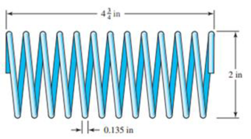
Consider the steel spring in the illustration.
- (a) Find the pitch, solid height, and number of active turns.
- (b) Find the spring rate. Assume the material is A227 HD steel.
- (c) Find the force Fs required to close the spring solid.
- (d) Find the shear stress in the spring due to the force Fs.
Problem 10-20
Expert Solution & Answer
Want to see the full answer?
Check out a sample textbook solution
Students have asked these similar questions
A hand cranking lever, as shown in Figure 6 below, is used to start a truck engine byapplying a force F = 400 N. The material of the cranking lever has a yield strength = 320 MPa;Ultimate tensile strength = 500 MPa; Young’s modulus = 205 GPa; Modulus of rigidity = 84 GPaand poisson’s ratio = 0.3. Assuming factor of safety to be 4 based on yield strength, design thediameter of the lever at section X-X near the guide bush using: a) Maximum distortion energytheory; and b) Maximum shear stress theory.
THE ORIGINAL QUESTION IS: For the beam shown, find the reactions at the supports and plot the shear-force and bending-moment diagrams. Label the diagrams properly and provide values at all key points. THE QUESTION THAT NEEDS TO BE ANSWERED IS:
Repeat problem 3-5 using singularity functions exclusively (including reactions).
The shaft in the figure is mounted with a gear wheel key. Shaft material 42CrMo4 The weight of the gear on the shaft is 0.9 kg, dimension, surface and notch factors KbK / Kç = 0.83, shaft speed n = 1120 rpm, shaft transmitted power 7.5 kW, force on shaft Fn = F = 2680 N Since the desired safety coefficient is Ssafe = 2;
Draw the bending and torsional moment diagrams of the shaft.
Chapter 10 Solutions
SHIGLEY'S MECH.ENGIN....(LOOSE)>CUSTOM<
Ch. 10 - Within the range of recommended values of the...Ch. 10 - It is instructive to examine the question of the...Ch. 10 - A helical compression spring is wound using...Ch. 10 - The spring in Prob. 10-3 is to be used with a...Ch. 10 - A helical compression spring is made with...Ch. 10 - A helical compression spring is to be made of...Ch. 10 - A helical compression spring is made of hard-drawn...Ch. 10 - The spring of Prob. 107 is to be used with a...Ch. 10 - 109 to 1019 Listed in the tables are six springs...Ch. 10 - 109 to 1019 Listed in the tables are six springs...
Ch. 10 - 10-9 to 10-19 Listed in the tables are six springs...Ch. 10 - Prob. 12PCh. 10 - 10-9 to 10-19 Listed in the tables are six springs...Ch. 10 - 10-9 to 10-19 Listed in the tables are six springs...Ch. 10 - 10-9 to 10-19 Listed in the tables are six springs...Ch. 10 - 10-9 to 10-19 Listed in the tables are six springs...Ch. 10 - Prob. 17PCh. 10 - 10-9 to 10-19 Listed in the tables are six springs...Ch. 10 - 10-9 to 10-19 Listed in the tables are six springs...Ch. 10 - Consider the steel spring in the illustration. (a)...Ch. 10 - A static service music wire helical compression...Ch. 10 - Solve Prob. 1021 by iterating with an initial...Ch. 10 - A holding fixture for a workpiece 37.5 mm thick at...Ch. 10 - Solve Prob. 10-23 by iterating with an initial...Ch. 10 - A compression spring is needed to fit over a...Ch. 10 - A compression spring is needed to fit within a...Ch. 10 - A helical compression spring is to be cycled...Ch. 10 - The figure shows a conical compression helical...Ch. 10 - A helical coil compression spring is needed for...Ch. 10 - Solve Prob. 10-30 using the Goodman-Zimmerli...Ch. 10 - Solve Prob. 10-30 using the Sines-Zimmerli...Ch. 10 - Design the spring of Ex. 10-5 using the...Ch. 10 - Solve Prob. 10-33 using the Goodman-Zimmerli...Ch. 10 - A hard-drawn spring steel extension spring is to...Ch. 10 - The extension spring shown in the figure has...Ch. 10 - Design an infinite-life helical coil extension...Ch. 10 - Prove Eq. (10-40). Hint: Using Castigliunos...Ch. 10 - The figure shows a finger exerciser used by...Ch. 10 - The rat trap shown in the figure uses two...Ch. 10 - Prob. 41PCh. 10 - Prob. 42PCh. 10 - Figure 10-13b shows a spring of constant thickness...
Knowledge Booster


Learn more about
Need a deep-dive on the concept behind this application? Look no further. Learn more about this topic, mechanical-engineering and related others by exploring similar questions and additional content below.Similar questions
- What is the maximum power that can be delivered by a hollow propeller shaft (outside diameter 50 mm, inside diameter 40 mm, and shear modulus of elasticity 80 GPa) turning at 600 rpm if the allowable shear stress is 100 MPa and the allowable rate of twist is 3.0°/m?arrow_forwardA motor driving a solid circular steel shaft with diameter d = 1.5 in, transmits 50 hp to a gear at B, The allowable shear stress in the steel is 6000 psi. Calculate the required speed of rotation (number of revolutions per minute) so that the shear stress in the shaft does not exceed the allowable limit.arrow_forwardCompare the angle of twist 1 for a thin-walled circular tube (see figure) calculated from the approximate theory for thin-walled bars with the angle of twist 2 calculated from the exact theory of torsion for circular bars, Express the ratio 12terms of the non-dimensional ratio ß = r/t. Calculate the ratio of angles of twist for ß = 5, 10, and 20. What conclusion about the accuracy of the approximate theory do you draw from these results?arrow_forward
- Repeat Problem 10.3-15 using L = 3.5 m, max = 3 mm, and EI = 800 kN·m2.arrow_forwardA heavy flywheel rotating at n revolutions per minute is rigidly attached to the end of a shaft of diameter d (see figure). If the bearing at A suddenly freezes, what will be the maximum angle of twist <£of the shaft? What is the corresponding maximum shear stress in the shaft? (Let L = length of the shaft, G = shear modulus of elasticity, and / = mass moment of inertia of the flywheel about the axis of the shaft. Also, disregard friction in the bearings at Sand Cand disregard the mass of the shaft.) Hint: Equate the kinetic energy of the rotating flywheel to the strain energy of the shaft.arrow_forwardSolve the preceding problem for the following data:P = 160 kN,JV = 200 tN,L = 2 m,b = 95 mm, h = 300 mm, and d = 200 mmarrow_forward
- A crank arm consists of a solid segment of length bxand diameter rf, a segment of length bltand a segment of length byas shown in the figure. Two loads P act as shown: one parallel to — vand another parallel to —y. Each load P equals 1.2 kN. The crankshaft dimensions are A] = 75 mm, fr> = 125 mm, and b3= 35 mm. The diameter of the upper shaft isd = 22 mm, (a) Determine the maximum tensile, compressive, and shear stresses at point A, which is located on the surface of the shaft at the z axis. (b) Determine the maximum tensile, compressive, and shear stresses at point B, which is located on the surface of the shaft at the y axisarrow_forwardA polyethylene tube (length L) has a cap that when installed compresses a spring (with under-formed length L1) by an amount ?? = (L1 = L). Ignore deformations of the cap and base. Use the force at the base of the spring as the redundant. Use numerical properties given in the boxes. (a) What is the resulting Force-in the spring, Fk? (b) What is the resulting Force in the tube, Ftl (c) What is the filial length of the tube, Lf? (d) What temperature change ?T inside the tube will result in zero force in the springarrow_forwardA bumper for a mine car is constructed with a spring of stiffness k = 1120 lb/in. (see figure). If a car weighing 3450 lb is traveling at velocity v = 7 mph when it strikes the spring, what is the maximum shortening of the spring?arrow_forward
- Repeat Problem 3.3-1, but now use a circular tube with outer diameter d0= 2.5 in. and inner diameter di= 1.5 in.arrow_forwardThe shaft in the figure is mounted with a gear wheel key. Shaft material 42CrMo4 The weight of the gear on the shaft is 0.9 kg, dimension, surface and notch factors KbK / Kç = 0.83, shaft speed n = 1120 rpm, shaft transmitted power 7.5 kW, force on shaft Fn = F = 2680 N Since the desired safety coefficient is Ssafe = 2; Check the safety of the shaftarrow_forwardA HELICAL SPRING HAS A STIFFNESS OF 25 kN/m. IF A MASS OF 100kg IS ATTACHED TO ITS FREE END, PULLED DOWN, AND THENRELEASED, Req: (draw the figure first before solving the problem)A. FIND THE AMOUNT OF DEFLECTION, IN CM,B. DETERMINE THE PERIODIC TIME OF ITS MOTION,C. IF THE MAXIMUM DEFLECTION WAS 50 mm, FIND THEVELOCITY,D. FIND THE ACCELERATION OF THE MASS WHEN ITS IS 300 mmFROM THE EQUILIBRIUM POSITION.arrow_forward
arrow_back_ios
SEE MORE QUESTIONS
arrow_forward_ios
Recommended textbooks for you
 Mechanics of Materials (MindTap Course List)Mechanical EngineeringISBN:9781337093347Author:Barry J. Goodno, James M. GerePublisher:Cengage Learning
Mechanics of Materials (MindTap Course List)
Mechanical Engineering
ISBN:9781337093347
Author:Barry J. Goodno, James M. Gere
Publisher:Cengage Learning
moment of inertia; Author: NCERT OFFICIAL;https://www.youtube.com/watch?v=A4KhJYrt4-s;License: Standard YouTube License, CC-BY