
Concept explainers
Videos
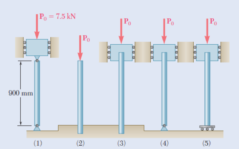
Each of the five struts shown consists of a solid steel rod. (a) Knowing that the strut of Fig. (1) is of a 20-mm diameter, determine the factor of safety with respect to buckling for the loading shown. (b) Determine the diameter of each of the other struts for which the factor of safety is the same as the factor of safety obtained in part a. Use E = 200 GPa.
Fig. P10.27
(a)
Find the factor of safety with respect to buckling.
Answer to Problem 27P
The factor of safety with respect to buckling is
Explanation of Solution
The dimeter of the strut (1) is
The centric load in the strut (1) is
The modulus of elasticity of the column is
Determine the moment of inertia of the strut (1)
Here, the diameter of the strut 1 is
Substitute 20 mm for
Both the ends are pin connected.
The effective length of the column
Determine the critical load
Here, the modulus of elasticity is E.
Substitute 200 GPa for E,
Determine the factor of safety (FOS) using the relation.
Here, the allowable load in strut 1 is
Substitute 19.14 kN for
Therefore, the factor of safety with respect to buckling is
(b)
Find the diameter of the other struts for the condition that the factor of safety is same.
Answer to Problem 27P
The diameter of the strut (2) is
The diameter of the strut (3) is
The diameter of the strut (4) is
The diameter of the strut (5) is
Explanation of Solution
Determine the factor of safety (FOS) using the relation.
Therefore, the factor of safety is directly proportional to the critical load.
Here, the moment of inertia of ith strut is
Strut (2);
Show the effective length of the strut (2) as in Figure 1.
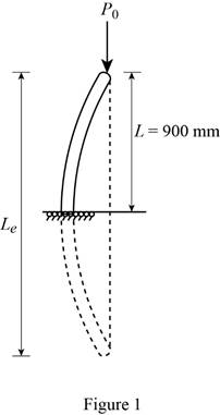
The effective length of the strut (2) is twice the length of the strut (1).
Substitute 2 for i, 2L for
Therefore, the diameter of the strut (2) is
Strut (3);
Show the effective length of the strut (3) as in Figure 2.
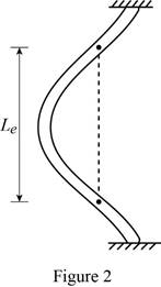
The effective length of the strut (3) is half the length of the strut (1).
Substitute 3 for i,
Therefore, the diameter of the strut (3) is
Strut (4);
Show the effective length of the strut (4) as in Figure 3.
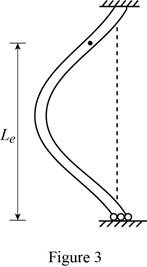
The effective length of the strut (4) is 0.7 times the length of the strut (1).
Substitute 4 for i,
Therefore, the diameter of the strut (4) is
Strut (5);
Show the effective length of the strut (5) as in Figure 4.
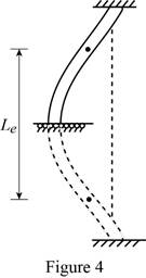
The effective length of the strut (5) is equal to the length of the strut (1).
Substitute 5 for i, L for
Therefore, the diameter of the strut (5) is
Want to see more full solutions like this?
Chapter 10 Solutions
Connect 1-semester Access Card For Mechanics Of Materials - 2016 Update


- (a) Considering only buckling in the plane of the structure shown and using Euler’s formula, determine the value of θbetween 0 and 90° for which the allowable magnitude of the load P is maximum. (b) Determine the corresponding maximum value of P knowing that a factor of safety of 3.2 is required. Use E= 29 x 106 psi.arrow_forwardA column with the cross section shown has a 13.5-ft effective length. Using a factor of safety equal to 2.8, determine the allowable centric load that can be applied to the column. Use E= 29 x106 psi.arrow_forwardColumn ABC has a uniform rectangular cross section with b=12 mm and d=22 mm. The column is braced in the xz plane at its midpoint C and carries a centric load P of magnitude 3.8 kN. Knowing that a factor of safety of 3.2 is required, determine the largest allowable length L. Use E=200 GPaarrow_forward
- Each of the two vertical links CF connecting the two horizontal members AD and EG has a 10x40-mm uniform rectangular cross section and is made of a steel with an ultimate strength in tension of 400 MPa,while each of the pins at C and F has a 20-mm diameter and is made of a steel with an ultimate strength in shear of 150 MPa. Determine the overall factor of safety for the links CF and the pins connecting them to the horizontal members.arrow_forwardThe length of the 332332 -in.-diameter steel wire CD has been adjusted so that with no load applied, a gap of 116116 in. exists between the end B of the rigid beam ACB and contact point E. Knowing that E = 29 × 106 psi, determine where a 57-lb (w) block should be placed on the beam in order to cause contact between B and E. For contact, x < in.arrow_forwardA column of 22-ft effective length is to be made by welding two 9 *0.5-in. plates to a W8 * 35 rolled steel shape as shown. Determine the allowable centric load if a factor of safety 2.3 is required. Use E=29 *106 psiarrow_forward
- THe bracket shown is made of cold drawn steel with Sy=400MPa and Su=480 MPa, and is fastened to a beam made of the same material by five rivets that are made of a steel with Sy=300 MPa and Sut=365 MPa. The thickness of the bracket and the beam are 12 mm and 16 mm respectively.Diameters of the rivets are 20 mm. What safe load F(steady) can be supported by the riveted joint for a factor of safety of 2. Use distortion energy theory of failure.arrow_forwardAn aluminum column with a length of L and a rectangular cross-section has a fixed end B and supports a centric load at A. Two smooth and rounded fixed plates restrain end a from moving in one of the vertical planes of symmetry of the column but allow it to move in the other plane. (a) Determine the ratio a/b of the two sides of the cross section corresponding to the most efficient design against buckling. (b) Design the most efficient cross section for the column, knowing that L = 20in., E=10.1 x 10^6 psi, P = 5kips, and a factor of safety of 2.5 is required. Now, replace the pinned boundary condition on top with a fixed boundary condition. You otherwise leave all other aspects of the problem unchanged.arrow_forwardAn aluminum column with a length of L and a rectangular cross-section has a fixed end B and supports a centric load at A. Two smooth and rounded fixed plates restrain end a from moving in one of the vertical planes of symmetry of the column but allow it to move in the other plane. (a) Determine the ratio a/b of the two sides of the cross section corresponding to the most efficient design against buckling. (b) Design the most efficient cross section for the column, knowing that L = 20in., E=10.1 x 10^6 psi, P = 5kips, and a factor of safety of 2.5 is required. Consider Sample Problem 10.1. Solve the same problem, but this time replace the pinned boundary condition on top with a fixed boundary condition. You otherwise leave all other aspects of the problem unchanged. Be sure to answer both Part a and Part b. As careful observation, please do keep in mind that two things happen: First, on top, the pinned boundary condition in one place is replaced by the fixed boundary condition in that…arrow_forward
- A rectangular cross section steel column of length L, a fixed end at B and supports a concentric load at A as shown. Point A is restrained from moving in one of the vertical planes of symmetry of the column, but allows to move in the other plane by the use of two smooth and rounded fixed plates.(a) Determine the ratio a/b of the two sides of the cross section corresponding to the most efficient design against buckling.(b) Design the most efficient cross section for the column, knowing that L = 45 in., E = 10 x 106 psi, P = 20 kips, and that a factor of safety of 2.7 is required. Answers: (a) _______ (b) _______arrow_forwardA glue-laminated column of 3-m effective length is to be made from boards of 24 x 100-mm cross section. Knowing that for the grade of wood used, E= 11 GPa and the adjusted allowable stress for com-pression parallel to the grain is σC= 9 MPa, determine the number of boards that must be used to support the centric load shown when (a) P= 34 kN, (b) P= 17 kNarrow_forwardThe horizontal link BC is 6.35 mm thick, has a width w = 31.8 mm, and is made of steel with ultimate tensile strength equal to 483 MPa. What should be the factor of safety to be used if the structure shown is designed to support a load P = 44.5 kN.arrow_forward
 Elements Of ElectromagneticsMechanical EngineeringISBN:9780190698614Author:Sadiku, Matthew N. O.Publisher:Oxford University Press
 Mechanics of Materials (10th Edition)Mechanical EngineeringISBN:9780134319650Author:Russell C. HibbelerPublisher:PEARSON
 Thermodynamics: An Engineering ApproachMechanical EngineeringISBN:9781259822674Author:Yunus A. Cengel Dr., Michael A. BolesPublisher:McGraw-Hill Education
 Control Systems EngineeringMechanical EngineeringISBN:9781118170519Author:Norman S. NisePublisher:WILEY
 Mechanics of Materials (MindTap Course List)Mechanical EngineeringISBN:9781337093347Author:Barry J. Goodno, James M. GerePublisher:Cengage Learning
 Engineering Mechanics: StaticsMechanical EngineeringISBN:9781118807330Author:James L. Meriam, L. G. Kraige, J. N. BoltonPublisher:WILEY