
Concept explainers
Videos
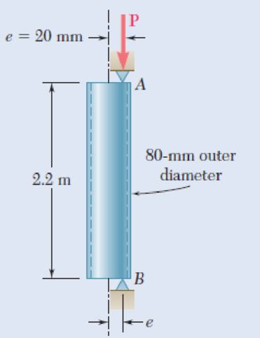
A steel tube of 80-mm outer diameter is to carry a 93-kN load P with an eccentricity of 20 mm. The tubes available for use are made with wall thicknesses in increments of 3 mm from 6 mm to 15 mm. Using the allowable-stress method, determine the lightest tube that can be used. Assume E = 200 GPa and σY = 250 MPa.
Fig. P10.105
Find the thickness of the lightest tube.
Answer to Problem 105P
The thickness of the lightest steel tube is
Explanation of Solution
Given information:
The length of the steel tube is
The outer diameter of the steel tube is
The magnitude of the axial load is
The eccentricity of the load in steel tube is
The allowable yield stress of the steel tube is
The modulus of elasticity of the steel tube is
Calculation:
The effective length of the column
Find the inner diameter of the steel tube
Here, the thickness of the steel tube is t.
Substitute 80 mm for
Find the cross sectional area of the steel tube (A) using the equation.
Substitute 80 mm for
Find the moment of inertia of the steel tube (I) using the equation.
Substitute 80 mm for
Find the minimum radius of gyration (r) using the relation.
Substitute
Find the distance between the neutral axis to the extreme fibre (c) using the relation.
Substitute 80 mm for
Find the slenderness ratio
Here, the modulus of elasticity of the material is E and the allowable yield strength is
Substitute 200 GPa for E and 250 MPa for
Find the ratio of the effective length to the minimum radius of gyration.
Consider
Find the effective stress
Substitute 200 GPa for E and
Find the critical stress
Substitute 250 MPa for
Find the allowable stress
Substitute
Find the maximum moment (M) using the relation.
Here, the allowable load is P and the eccentricity of the load is e.
Substitute 93 kN for P and 20 mm for e.
Find the thickness of the lightest tube (t) using the equation.
Substitute
Solve the equation;
The thickness is
The nearest 3 mm increment of the thickness is 12 mm.
Check:
Substitute 12 mm for t in Equation (1).
Therefore, the thickness of the lightest steel tube is
Want to see more full solutions like this?
Chapter 10 Solutions
Connect 1-semester Access Card For Mechanics Of Materials - 2016 Update


- A 2-m length of an aluminum pipe of 240-mm outer diameter and 10-mm wall thickness is used as a short column to carry a 640-kN centric axial load. Knowing that E= 73 GPa and ν=0.33, determine (a) the change in length of the pipe, (b) the change in its outer diam-eter, (c) the change in its wall thicknessarrow_forwardA glue-laminated column of 3-m effective length is to be made from boards of 24 x 100-mm cross section. Knowing that for the grade of wood used, E= 11 GPa and the adjusted allowable stress for com-pression parallel to the grain is σC= 9 MPa, determine the number of boards that must be used to support the centric load shown when (a) P= 34 kN, (b) P= 17 kNarrow_forwardColumn ABC has a uniform rectangular cross section and is braced in the xz plane at its midpoint C. (a) Determine the ratio b/d for which the factor of safety is the same with respect to buckling in the xz and yz planes. (b) Using the ratio found in part a, design the cross section of the column so that the factor of safety will be 3.0 when P= 4.4 kN, L=1 m, and E=200 GPaarrow_forward
- In the steel structure shown, a 6-mm-diameter pin is used at C and 12-mm-diameter pins are used at B and D. The ultimate shearing stress is 150 MPa at all connections, and the ultimate normal stress is 350 MPa in link BD. Knowing that a factor of safety of 3.0 is desired, determine the largest load P that can be applied at A. Note that link BD is not reinforced around the pin holes. The largest load P that can be applied at A is kN.arrow_forwardIn the steel structure shown, a 6-mm-diameter pin is used at C and10-mm-diameter pins are used at B and D. The ultimate shearing stress is 150 MPa at all connections, and the ultimate normal stress is 400 MPa in link BD. Knowing that a factor of safety of 3.0 is desired,determine the largest load P that can be applied at A. Note that link BD is not reinforced around the pin holes.arrow_forwardIn the structure shown, an 8-mm-diameter pin is used at A, and 12-mm-diameter pins are used at B and D. Knowing that the ultimate shearing stress is 100 MPa at all connections and that the ultimate normal stress is 250 MPa in each of the two links joining B and D, determine the allowable load P if an overall factor of safety of 2.6 is desired.arrow_forward
- A load P is supported as shown by a steel pin that has been inserted in a short wooden member hanging from the ceiling. The ultimate strength of the wood used is 60 MPa in tension and 7.5 MPa in shear,while the ultimate strength of the steel is 145 MPa in shear. Knowing that b = 40 mm, c = 55 mm, and d = 12 mm, determine the load P if an overall factor of safety of 3.2 is desired.arrow_forwardIn the structure shown, an 8-mm-diameter pin is used at A and 12 mmdiameter pins are used at B and D. Knowing that the ultimate shearingstress is 100 MPa at all connections and the ultimate normal stress is 250 MPa in each of the two links joining B and D, determine the allowable load P if an overall factor of safety of 3.0 is desired.arrow_forwardDetermine the values of the stress in portions AC and CB of the steel bar shown Fig. when the temperature of the bar is 2508F, knowing that a close fit exists at both of the rigid supports when the temperature is 1758F. Use the values E=29 *106 psi and α=6.5 * 10–6/8F for steelarrow_forward
- A piping tube with an outside diameter of 50 mm and wall thickness of 5 mm is used as a compression member. Determine the maximum load P that the member can support if the normal stress in the member must be limited to 120 MPa.arrow_forwardIn the structure shown, an 8-mm diameter pin is used at A, and 12- mm diameter pins are used at B and D. Knowing that the ultimate shearing stresses is 100 MPa at all connections and that the ultimate normal stress is 250 MPa in each of the two links joining B and D, determine the allowable load P if an overall factor of safety of 3.0 is desired.arrow_forwardTHe bracket shown is made of cold drawn steel with Sy=400MPa and Su=480 MPa, and is fastened to a beam made of the same material by five rivets that are made of a steel with Sy=300 MPa and Sut=365 MPa. The thickness of the bracket and the beam are 12 mm and 16 mm respectively.Diameters of the rivets are 20 mm. What safe load F(steady) can be supported by the riveted joint for a factor of safety of 2. Use distortion energy theory of failure.arrow_forward
 Elements Of ElectromagneticsMechanical EngineeringISBN:9780190698614Author:Sadiku, Matthew N. O.Publisher:Oxford University Press
 Mechanics of Materials (10th Edition)Mechanical EngineeringISBN:9780134319650Author:Russell C. HibbelerPublisher:PEARSON
 Thermodynamics: An Engineering ApproachMechanical EngineeringISBN:9781259822674Author:Yunus A. Cengel Dr., Michael A. BolesPublisher:McGraw-Hill Education
 Control Systems EngineeringMechanical EngineeringISBN:9781118170519Author:Norman S. NisePublisher:WILEY
 Mechanics of Materials (MindTap Course List)Mechanical EngineeringISBN:9781337093347Author:Barry J. Goodno, James M. GerePublisher:Cengage Learning
 Engineering Mechanics: StaticsMechanical EngineeringISBN:9781118807330Author:James L. Meriam, L. G. Kraige, J. N. BoltonPublisher:WILEY