
Mechanics of Materials, 7th Edition
7th Edition
ISBN: 9780073398235
Author: Ferdinand P. Beer, E. Russell Johnston Jr., John T. DeWolf, David F. Mazurek
Publisher: McGraw-Hill Education
expand_more
expand_more
format_list_bulleted
Concept explainers
Videos
Textbook Question
Chapter 10.2, Problem 47P
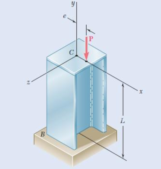
A 100-kN axial load P is applied to the W150 × 18 rolled-steel column BC that is free at its top C and fixed at its base B. Knowing that the eccentricity of the load is e = 6 mm, determine the largest permissible length L if the allowable stress in the column is 80 MPa. Use E = 200 GPa.
Fig. 10.47
Expert Solution & Answer
Want to see the full answer?
Check out a sample textbook solution
Students have asked these similar questions
Determine the largest axial load P that can be safely supported by a flat steel bar consisting of two portions, both 10 mm thick and, respectively, 40 and 80 mm wide, connected by fillets of radius r=4 mm. Assume an allowable normal stress of 180 MPa.
Column ABC has a uniform rectangular cross section with b=12 mm and d=22 mm. The column is braced in the xz plane at its midpoint C and carries a centric load P of magnitude 3.8 kN. Knowing that a factor of safety of 3.2 is required, determine the largest allowable length L. Use E=200 GPa
The length of the 332332 -in.-diameter steel wire CD has been adjusted so that with no load applied, a gap of 116116 in. exists between the end B of the rigid beam ACB and contact point E. Knowing that E = 29 × 106 psi, determine where a 57-lb (w) block should be placed on the beam in order to cause contact between B and E. For contact, x < in.
Chapter 10 Solutions
Mechanics of Materials, 7th Edition
Ch. 10.1 - Knowing that the spring at A is of constant k and...Ch. 10.1 - Two rigid bars AC and BC are connected by a pin at...Ch. 10.1 - 10.3 and 10.4 Two rigid bars AC and BC are...Ch. 10.1 - 10.3 and 10.4 Two rigid bars AC and BC are...Ch. 10.1 - The steel rod BC is attached to the rigid bar AB...Ch. 10.1 - The rigid rod AB is attached to a hinge at A and...Ch. 10.1 - The rigid bar AD is attached to two springs of...Ch. 10.1 - A frame consists of four L-shaped members...Ch. 10.1 - Determine the critical load of a pin-ended steel...Ch. 10.1 - Determine the critical load of a pin-ended wooden...
Ch. 10.1 - A column of effective length L can be made by...Ch. 10.1 - A compression member of 1.5-m effective length...Ch. 10.1 - Determine the radius of the round strut so that...Ch. 10.1 - Determine (a) the critical load for the square...Ch. 10.1 - A column with the cross section shown has a...Ch. 10.1 - A column is made from half of a W360 216...Ch. 10.1 - A column of 22-ft effective length is made by...Ch. 10.1 - A single compression member of 8.2-m effective...Ch. 10.1 - Knowing that P = 5.2 kN, determine the factor of...Ch. 10.1 - Members AB and CD are 30-mm-diameter steel rods,...Ch. 10.1 - The uniform brass bar AB has a rectangular cross...Ch. 10.1 - A 1-in.-square aluminum strut is maintained in the...Ch. 10.1 - A 1-in.-square aluminum strut is maintained in the...Ch. 10.1 - Column ABC has a uniform rectangular cross section...Ch. 10.1 - Column ABC has a uniform rectangular cross section...Ch. 10.1 - Column AB carries a centric load P of magnitude 15...Ch. 10.1 - Each of the five struts shown consists of a solid...Ch. 10.1 - A rigid block of mass m can be supported in each...Ch. 10.2 - An axial load P = 15 kN is applied at point D that...Ch. 10.2 - An axial load P is applied to the 32-mm-diameter...Ch. 10.2 - The line of action of the 310-kN axial load is...Ch. 10.2 - Prob. 32PCh. 10.2 - An axial load P is applied to the 32-mm-square...Ch. 10.2 - Prob. 34PCh. 10.2 - Prob. 35PCh. 10.2 - Prob. 36PCh. 10.2 - Solve Prob. 10.36, assuming that the axial load P...Ch. 10.2 - The line of action of the axial load P is parallel...Ch. 10.2 - Prob. 39PCh. 10.2 - Prob. 40PCh. 10.2 - The steel bar AB has a 3838-in. square cross...Ch. 10.2 - For the bar of Prob. 10.41, determine the required...Ch. 10.2 - A 3.5-m-long steel tube having the cross section...Ch. 10.2 - Prob. 44PCh. 10.2 - An axial load P is applied to the W8 28...Ch. 10.2 - Prob. 46PCh. 10.2 - A 100-kN axial load P is applied to the W150 18...Ch. 10.2 - A 26-kip axial load P is applied to a W6 12...Ch. 10.2 - Prob. 49PCh. 10.2 - Axial loads of magnitude P = 84 kN are applied...Ch. 10.2 - An axial load of magnitude P = 220 kN is applied...Ch. 10.2 - Prob. 52PCh. 10.2 - Prob. 53PCh. 10.2 - Prob. 54PCh. 10.2 - Axial loads of magnitude P = 175 kN are applied...Ch. 10.2 - Prob. 56PCh. 10.3 - Using allowable stress design, determine the...Ch. 10.3 - Prob. 58PCh. 10.3 - Prob. 59PCh. 10.3 - A column having a 3.5-m effective length is made...Ch. 10.3 - Prob. 61PCh. 10.3 - Bar AB is free at its end A and fixed at its base...Ch. 10.3 - Prob. 63PCh. 10.3 - Prob. 64PCh. 10.3 - A compression member of 8.2-ft effective length is...Ch. 10.3 - A compression member of 9-m effective length is...Ch. 10.3 - A column of 6.4-m effective length is obtained by...Ch. 10.3 - A column of 21-ft effective length is obtained by...Ch. 10.3 - Prob. 69PCh. 10.3 - Prob. 70PCh. 10.3 - Prob. 71PCh. 10.3 - Prob. 72PCh. 10.3 - Prob. 73PCh. 10.3 - For a rod made of aluminum alloy 2014-T6, select...Ch. 10.3 - Prob. 75PCh. 10.3 - Prob. 76PCh. 10.3 - A column of 4.6-m effective length must carry a...Ch. 10.3 - A column of 22.5-ft effective length must carry a...Ch. 10.3 - Prob. 79PCh. 10.3 - A centric load P must be supported by the steel...Ch. 10.3 - A square steel tube having the cross section shown...Ch. 10.3 - Prob. 82PCh. 10.3 - Prob. 83PCh. 10.3 - Two 89 64-mm angles are bolted together as shown...Ch. 10.3 - Prob. 85PCh. 10.3 - Prob. 86PCh. 10.3 - Prob. 87PCh. 10.3 - Prob. 88PCh. 10.4 - An eccentric load is applied at a point 22 mm from...Ch. 10.4 - Prob. 90PCh. 10.4 - Prob. 91PCh. 10.4 - Solve Prob. 10.91 using the interaction method and...Ch. 10.4 - A column of 5.5-m effective length is made of the...Ch. 10.4 - Prob. 94PCh. 10.4 - A steel compression member of 9-ft effective...Ch. 10.4 - Prob. 96PCh. 10.4 - Two L4 3 38-in. steel angles are welded together...Ch. 10.4 - Solve Prob. 10.97 using the interaction method...Ch. 10.4 - A rectangular column is made of a grade of sawn...Ch. 10.4 - Prob. 100PCh. 10.4 - Prob. 101PCh. 10.4 - Prob. 102PCh. 10.4 - Prob. 103PCh. 10.4 - Prob. 104PCh. 10.4 - A steel tube of 80-mm outer diameter is to carry a...Ch. 10.4 - Prob. 106PCh. 10.4 - Prob. 107PCh. 10.4 - Prob. 108PCh. 10.4 - Prob. 109PCh. 10.4 - Prob. 110PCh. 10.4 - Prob. 111PCh. 10.4 - Prob. 112PCh. 10.4 - Prob. 113PCh. 10.4 - Prob. 114PCh. 10.4 - Prob. 115PCh. 10.4 - A steel column of 7.2-m effective length is to...Ch. 10 - Determine (a) the critical load for the steel...Ch. 10 - Prob. 118RPCh. 10 - Prob. 119RPCh. 10 - (a) Considering only buckling in the plane of the...Ch. 10 - Member AB consists of a single C130 3 10.4 steel...Ch. 10 - The line of action of the 75-kip axial load is...Ch. 10 - Prob. 123RPCh. 10 - Prob. 124RPCh. 10 - A rectangular column with a 4.4-m effective length...Ch. 10 - Prob. 126RPCh. 10 - Prob. 127RPCh. 10 - Prob. 128RP
Knowledge Booster


Learn more about
Need a deep-dive on the concept behind this application? Look no further. Learn more about this topic, mechanical-engineering and related others by exploring similar questions and additional content below.Similar questions
- A column with the cross section shown has a 13.5-ft effective length. Using a factor of safety equal to 2.8, determine the allowable centric load that can be applied to the column. Use E= 29 x106 psi.arrow_forwardA 2-m length of an aluminum pipe of 240-mm outer diameter and 10-mm wall thickness is used as a short column to carry a 640-kN centric axial load. Knowing that E= 73 GPa and ν=0.33, determine (a) the change in length of the pipe, (b) the change in its outer diam-eter, (c) the change in its wall thicknessarrow_forwardA glue-laminated column of 3-m effective length is to be made from boards of 24 x 100-mm cross section. Knowing that for the grade of wood used, E= 11 GPa and the adjusted allowable stress for com-pression parallel to the grain is σC= 9 MPa, determine the number of boards that must be used to support the centric load shown when (a) P= 34 kN, (b) P= 17 kNarrow_forward
- Determine the values of the stress in portions AC and CB of the steel bar shown Fig. when the temperature of the bar is 2508F, knowing that a close fit exists at both of the rigid supports when the temperature is 1758F. Use the values E=29 *106 psi and α=6.5 * 10–6/8F for steelarrow_forwardThe steel frame shown has a diagonal brace BD with an area of 1548 sq.mm. Determine the largest allowable load P (in N) if the change in length of member BD is not to exceed 1.35 mm. Use x = 4.59m, y = 5.76m, and E = 199.3 Gpa. Express your answer in four decimal places.arrow_forwardKnowing that a 0.02-in. gap exists when the temperature is 75°F, determine (a) the temperature at which the normal stress in the alumi-num bar will be equal to –11 ksi, (b) the corresponding exact length of the aluminum bar.arrow_forward
- Two links BF are made of steel with a 450-MPa ultimate normal stress and has a 6x12–mm uniform rectangular cross section. Links BF are connected to members ABD and CDEF by 8-mm diameter pins; ABD and CDEF are connected together by a 10-mm diameter pin; CDEF is connected to the support by a 10-mm diameter pin; all of the pins are made of steel with a 170 MPa ultimate shearing stress. Knowing that a factor of safety of 3 is desired, determine the largest load P that may be appliedarrow_forwardEach of the two vertical links CF connecting the two horizontal members AD and EG has a 10x40-mm uniform rectangular cross section and is made of a steel with an ultimate strength in tension of 400 MPa,while each of the pins at C and F has a 20-mm diameter and is made of a steel with an ultimate strength in shear of 150 MPa. Determine the overall factor of safety for the links CF and the pins connecting them to the horizontal members.arrow_forwardKnowing that connecting rod BD has a uniform cross section of area equal to 800 mm², determine the magnitude of the load P so that the normal stress in rod BD is 50 MPa.arrow_forward
- Three wires are used to suspend the plate shown. Aluminum wires of 18-in. diameter are used at A and Bwhile a steel wire of 112-in. diameter is used at C. Knowing that the allowable stress for aluminum (Ea510.4 3 106 psi) is 14 ksi and that the allowable stress for steel (Es529 3 106 psi) is 18 ksi, determine the maximum load P that can be appliedarrow_forwardA load P is supported as shown by a steel pin that has been inserted in a short wooden member hanging from the ceiling. The ultimate strength of the wood used is 60 MPa in tension and 7.5 MPa in shear,while the ultimate strength of the steel is 145 MPa in shear. Knowing that b = 40 mm, c = 55 mm, and d = 12 mm, determine the load P if an overall factor of safety of 3.2 is desired.arrow_forwardKnowing that the average normal stress in member EF of the Pratt bridge truss shown must not exceed 8.36 ksi for the given loading, determine the cross-sectional area (in sq. in) of this member that will yield the most economical and safe design if h = 14.2 ft and P = 87.28 kips.arrow_forward
arrow_back_ios
SEE MORE QUESTIONS
arrow_forward_ios
Recommended textbooks for you
 Elements Of ElectromagneticsMechanical EngineeringISBN:9780190698614Author:Sadiku, Matthew N. O.Publisher:Oxford University Press
 Mechanics of Materials (10th Edition)Mechanical EngineeringISBN:9780134319650Author:Russell C. HibbelerPublisher:PEARSON
 Thermodynamics: An Engineering ApproachMechanical EngineeringISBN:9781259822674Author:Yunus A. Cengel Dr., Michael A. BolesPublisher:McGraw-Hill Education
 Control Systems EngineeringMechanical EngineeringISBN:9781118170519Author:Norman S. NisePublisher:WILEY
 Mechanics of Materials (MindTap Course List)Mechanical EngineeringISBN:9781337093347Author:Barry J. Goodno, James M. GerePublisher:Cengage Learning
 Engineering Mechanics: StaticsMechanical EngineeringISBN:9781118807330Author:James L. Meriam, L. G. Kraige, J. N. BoltonPublisher:WILEY
Elements Of Electromagnetics
Mechanical Engineering
ISBN:9780190698614
Author:Sadiku, Matthew N. O.
Publisher:Oxford University Press
Mechanics of Materials (10th Edition)
Mechanical Engineering
ISBN:9780134319650
Author:Russell C. Hibbeler
Publisher:PEARSON
Thermodynamics: An Engineering Approach
Mechanical Engineering
ISBN:9781259822674
Author:Yunus A. Cengel Dr., Michael A. Boles
Publisher:McGraw-Hill Education
Control Systems Engineering
Mechanical Engineering
ISBN:9781118170519
Author:Norman S. Nise
Publisher:WILEY
Mechanics of Materials (MindTap Course List)
Mechanical Engineering
ISBN:9781337093347
Author:Barry J. Goodno, James M. Gere
Publisher:Cengage Learning
Engineering Mechanics: Statics
Mechanical Engineering
ISBN:9781118807330
Author:James L. Meriam, L. G. Kraige, J. N. Bolton
Publisher:WILEY
Column buckling; Author: Amber Book;https://www.youtube.com/watch?v=AvvaCi_Nn94;License: Standard Youtube License