
Mechanics of Materials, 7th Edition
7th Edition
ISBN: 9780073398235
Author: Ferdinand P. Beer, E. Russell Johnston Jr., John T. DeWolf, David F. Mazurek
Publisher: McGraw-Hill Education
expand_more
expand_more
format_list_bulleted
Concept explainers
Videos
Textbook Question
Chapter 10.1, Problem 12P
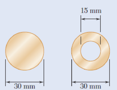
A compression member of 1.5-m effective length consists of a solid 30-mm-diameter brass rod. In order to reduce the weight of the member by 25%, the solid rod is replaced by a hollow rod of the cross section shown. Determine (a) the percent reduction in the critical load, (b) the value of the critical load for the hollow rod. Use E = 200 GPa.
Fig. P10.12
Expert Solution & Answer
Want to see the full answer?
Check out a sample textbook solution
Students have asked these similar questions
The length of the 332332 -in.-diameter steel wire CD has been adjusted so that with no load applied, a gap of 116116 in. exists between the end B of the rigid beam ACB and contact point E. Knowing that E = 29 × 106 psi, determine where a 57-lb (w) block should be placed on the beam in order to cause contact between B and E. For contact, x < in.
Determine the critical load of a pin-ended steel tube that is 5 m long and has a 100-mm outer diameter and a 16-mm wall thickness. Use E=200 GPa.
Column ABC has a uniform rectangular cross section and is braced in the xz plane at its midpoint C. (a) Determine the ratio b/d for which the factor of safety is the same with respect to buckling in the xz and yz planes. (b) Using the ratio found in part a, design the cross section of the column so that the factor of safety will be 3.0 when P= 4.4 kN, L=1 m, and E=200 GPa
Chapter 10 Solutions
Mechanics of Materials, 7th Edition
Ch. 10.1 - Knowing that the spring at A is of constant k and...Ch. 10.1 - Two rigid bars AC and BC are connected by a pin at...Ch. 10.1 - 10.3 and 10.4 Two rigid bars AC and BC are...Ch. 10.1 - 10.3 and 10.4 Two rigid bars AC and BC are...Ch. 10.1 - The steel rod BC is attached to the rigid bar AB...Ch. 10.1 - The rigid rod AB is attached to a hinge at A and...Ch. 10.1 - The rigid bar AD is attached to two springs of...Ch. 10.1 - A frame consists of four L-shaped members...Ch. 10.1 - Determine the critical load of a pin-ended steel...Ch. 10.1 - Determine the critical load of a pin-ended wooden...
Ch. 10.1 - A column of effective length L can be made by...Ch. 10.1 - A compression member of 1.5-m effective length...Ch. 10.1 - Determine the radius of the round strut so that...Ch. 10.1 - Determine (a) the critical load for the square...Ch. 10.1 - A column with the cross section shown has a...Ch. 10.1 - A column is made from half of a W360 216...Ch. 10.1 - A column of 22-ft effective length is made by...Ch. 10.1 - A single compression member of 8.2-m effective...Ch. 10.1 - Knowing that P = 5.2 kN, determine the factor of...Ch. 10.1 - Members AB and CD are 30-mm-diameter steel rods,...Ch. 10.1 - The uniform brass bar AB has a rectangular cross...Ch. 10.1 - A 1-in.-square aluminum strut is maintained in the...Ch. 10.1 - A 1-in.-square aluminum strut is maintained in the...Ch. 10.1 - Column ABC has a uniform rectangular cross section...Ch. 10.1 - Column ABC has a uniform rectangular cross section...Ch. 10.1 - Column AB carries a centric load P of magnitude 15...Ch. 10.1 - Each of the five struts shown consists of a solid...Ch. 10.1 - A rigid block of mass m can be supported in each...Ch. 10.2 - An axial load P = 15 kN is applied at point D that...Ch. 10.2 - An axial load P is applied to the 32-mm-diameter...Ch. 10.2 - The line of action of the 310-kN axial load is...Ch. 10.2 - Prob. 32PCh. 10.2 - An axial load P is applied to the 32-mm-square...Ch. 10.2 - Prob. 34PCh. 10.2 - Prob. 35PCh. 10.2 - Prob. 36PCh. 10.2 - Solve Prob. 10.36, assuming that the axial load P...Ch. 10.2 - The line of action of the axial load P is parallel...Ch. 10.2 - Prob. 39PCh. 10.2 - Prob. 40PCh. 10.2 - The steel bar AB has a 3838-in. square cross...Ch. 10.2 - For the bar of Prob. 10.41, determine the required...Ch. 10.2 - A 3.5-m-long steel tube having the cross section...Ch. 10.2 - Prob. 44PCh. 10.2 - An axial load P is applied to the W8 28...Ch. 10.2 - Prob. 46PCh. 10.2 - A 100-kN axial load P is applied to the W150 18...Ch. 10.2 - A 26-kip axial load P is applied to a W6 12...Ch. 10.2 - Prob. 49PCh. 10.2 - Axial loads of magnitude P = 84 kN are applied...Ch. 10.2 - An axial load of magnitude P = 220 kN is applied...Ch. 10.2 - Prob. 52PCh. 10.2 - Prob. 53PCh. 10.2 - Prob. 54PCh. 10.2 - Axial loads of magnitude P = 175 kN are applied...Ch. 10.2 - Prob. 56PCh. 10.3 - Using allowable stress design, determine the...Ch. 10.3 - Prob. 58PCh. 10.3 - Prob. 59PCh. 10.3 - A column having a 3.5-m effective length is made...Ch. 10.3 - Prob. 61PCh. 10.3 - Bar AB is free at its end A and fixed at its base...Ch. 10.3 - Prob. 63PCh. 10.3 - Prob. 64PCh. 10.3 - A compression member of 8.2-ft effective length is...Ch. 10.3 - A compression member of 9-m effective length is...Ch. 10.3 - A column of 6.4-m effective length is obtained by...Ch. 10.3 - A column of 21-ft effective length is obtained by...Ch. 10.3 - Prob. 69PCh. 10.3 - Prob. 70PCh. 10.3 - Prob. 71PCh. 10.3 - Prob. 72PCh. 10.3 - Prob. 73PCh. 10.3 - For a rod made of aluminum alloy 2014-T6, select...Ch. 10.3 - Prob. 75PCh. 10.3 - Prob. 76PCh. 10.3 - A column of 4.6-m effective length must carry a...Ch. 10.3 - A column of 22.5-ft effective length must carry a...Ch. 10.3 - Prob. 79PCh. 10.3 - A centric load P must be supported by the steel...Ch. 10.3 - A square steel tube having the cross section shown...Ch. 10.3 - Prob. 82PCh. 10.3 - Prob. 83PCh. 10.3 - Two 89 64-mm angles are bolted together as shown...Ch. 10.3 - Prob. 85PCh. 10.3 - Prob. 86PCh. 10.3 - Prob. 87PCh. 10.3 - Prob. 88PCh. 10.4 - An eccentric load is applied at a point 22 mm from...Ch. 10.4 - Prob. 90PCh. 10.4 - Prob. 91PCh. 10.4 - Solve Prob. 10.91 using the interaction method and...Ch. 10.4 - A column of 5.5-m effective length is made of the...Ch. 10.4 - Prob. 94PCh. 10.4 - A steel compression member of 9-ft effective...Ch. 10.4 - Prob. 96PCh. 10.4 - Two L4 3 38-in. steel angles are welded together...Ch. 10.4 - Solve Prob. 10.97 using the interaction method...Ch. 10.4 - A rectangular column is made of a grade of sawn...Ch. 10.4 - Prob. 100PCh. 10.4 - Prob. 101PCh. 10.4 - Prob. 102PCh. 10.4 - Prob. 103PCh. 10.4 - Prob. 104PCh. 10.4 - A steel tube of 80-mm outer diameter is to carry a...Ch. 10.4 - Prob. 106PCh. 10.4 - Prob. 107PCh. 10.4 - Prob. 108PCh. 10.4 - Prob. 109PCh. 10.4 - Prob. 110PCh. 10.4 - Prob. 111PCh. 10.4 - Prob. 112PCh. 10.4 - Prob. 113PCh. 10.4 - Prob. 114PCh. 10.4 - Prob. 115PCh. 10.4 - A steel column of 7.2-m effective length is to...Ch. 10 - Determine (a) the critical load for the steel...Ch. 10 - Prob. 118RPCh. 10 - Prob. 119RPCh. 10 - (a) Considering only buckling in the plane of the...Ch. 10 - Member AB consists of a single C130 3 10.4 steel...Ch. 10 - The line of action of the 75-kip axial load is...Ch. 10 - Prob. 123RPCh. 10 - Prob. 124RPCh. 10 - A rectangular column with a 4.4-m effective length...Ch. 10 - Prob. 126RPCh. 10 - Prob. 127RPCh. 10 - Prob. 128RP
Knowledge Booster


Learn more about
Need a deep-dive on the concept behind this application? Look no further. Learn more about this topic, mechanical-engineering and related others by exploring similar questions and additional content below.Similar questions
- Two links BF are made of steel with a 450-MPa ultimate normal stress and has a 6x12–mm uniform rectangular cross section. Links BF are connected to members ABD and CDEF by 8-mm diameter pins; ABD and CDEF are connected together by a 10-mm diameter pin; CDEF is connected to the support by a 10-mm diameter pin; all of the pins are made of steel with a 170 MPa ultimate shearing stress. Knowing that a factor of safety of 3 is desired, determine the largest load P that may be appliedarrow_forwardA load P is supported as shown by a steel pin that has been inserted in a short wooden member hanging from the ceiling. The ultimate strength of the wood used is 60 MPa in tension and 7.5 MPa in shear,while the ultimate strength of the steel is 145 MPa in shear. Knowing that b = 40 mm, c = 55 mm, and d = 12 mm, determine the load P if an overall factor of safety of 3.2 is desired.arrow_forwardA column of 22-ft effective length is to be made by welding two 9 *0.5-in. plates to a W8 * 35 rolled steel shape as shown. Determine the allowable centric load if a factor of safety 2.3 is required. Use E=29 *106 psiarrow_forward
- A 12-ft wooden rectangular column has the dimensions shown. Determine the critical load if the ends are assumed to be pin connected. E = 1.6(103) ksi. Yielding does not occur.arrow_forwardColumn ABC has a uniform rectangular cross section with b=12 mm and d=22 mm. The column is braced in the xz plane at its midpoint C and carries a centric load P of magnitude 3.8 kN. Knowing that a factor of safety of 3.2 is required, determine the largest allowable length L. Use E=200 GPaarrow_forwardTwo brass rods used as compression members, each of 3-m effective length, have the cross sections shown. (a) Determine the wall thick-ness of the hollow square rod for which the rods have the same cross-sectional area. (b) Using E= 105 GPa, determine the critical load of each rod.arrow_forward
- Each of the two vertical links CF connecting the two horizontal members AD and EG has a 10x40-mm uniform rectangular cross section and is made of a steel with an ultimate strength in tension of 400 MPa,while each of the pins at C and F has a 20-mm diameter and is made of a steel with an ultimate strength in shear of 150 MPa. Determine the overall factor of safety for the links CF and the pins connecting them to the horizontal members.arrow_forwardRigid bar ABC is supported by pin-connected bar (1). Bar (1) is 2.0-in. wide, 1.00-in. thick, and made of aluminum that has anelastic modulus of E = 12,000 ksi. Determine the maximum magnitude of load P that can be applied to the rigid bar withoutcausing member (1) to bucklearrow_forwardKnowing that the AB pillar shown below is supported at points A andB, determine the greatest load (w) that can be applied to the beam before the column starts tobe buckled or before the steel runs out. Consider leakage voltage = 250 MPa, E=200 GPa, F.S. = 1.5.arrow_forward
- Determine the critical load of a pin-ended wooden stick that is 3 ft long and has a 3/16 × 1 1/4-in. rectangular cross section. Use E = 1.6 × 10⁶ psi. (Round the final answer to two decimal places.)arrow_forwardA column of 3-m effective length is to be made by welding together two C130 *13 rolled-steel channels. Using E= 200 GPa, determine for each arrangement shown the allowable centric load if a factor of safety of 2.4 is required.arrow_forwardMember AB consists of a single C130 x 10.4 steel channel of length 2.5 m. Knowing that the pins at A and B pass through the centroid of the cross section of the channel, determine the factor of safety for the load shown with respect to buckling in the plane of the figure when θ= 30°. Use Euler’s formula with E= 200 GPa.arrow_forward
arrow_back_ios
SEE MORE QUESTIONS
arrow_forward_ios
Recommended textbooks for you
 Elements Of ElectromagneticsMechanical EngineeringISBN:9780190698614Author:Sadiku, Matthew N. O.Publisher:Oxford University Press
 Mechanics of Materials (10th Edition)Mechanical EngineeringISBN:9780134319650Author:Russell C. HibbelerPublisher:PEARSON
 Thermodynamics: An Engineering ApproachMechanical EngineeringISBN:9781259822674Author:Yunus A. Cengel Dr., Michael A. BolesPublisher:McGraw-Hill Education
 Control Systems EngineeringMechanical EngineeringISBN:9781118170519Author:Norman S. NisePublisher:WILEY
 Mechanics of Materials (MindTap Course List)Mechanical EngineeringISBN:9781337093347Author:Barry J. Goodno, James M. GerePublisher:Cengage Learning
 Engineering Mechanics: StaticsMechanical EngineeringISBN:9781118807330Author:James L. Meriam, L. G. Kraige, J. N. BoltonPublisher:WILEY
Elements Of Electromagnetics
Mechanical Engineering
ISBN:9780190698614
Author:Sadiku, Matthew N. O.
Publisher:Oxford University Press
Mechanics of Materials (10th Edition)
Mechanical Engineering
ISBN:9780134319650
Author:Russell C. Hibbeler
Publisher:PEARSON
Thermodynamics: An Engineering Approach
Mechanical Engineering
ISBN:9781259822674
Author:Yunus A. Cengel Dr., Michael A. Boles
Publisher:McGraw-Hill Education
Control Systems Engineering
Mechanical Engineering
ISBN:9781118170519
Author:Norman S. Nise
Publisher:WILEY
Mechanics of Materials (MindTap Course List)
Mechanical Engineering
ISBN:9781337093347
Author:Barry J. Goodno, James M. Gere
Publisher:Cengage Learning
Engineering Mechanics: Statics
Mechanical Engineering
ISBN:9781118807330
Author:James L. Meriam, L. G. Kraige, J. N. Bolton
Publisher:WILEY
Column buckling; Author: Amber Book;https://www.youtube.com/watch?v=AvvaCi_Nn94;License: Standard Youtube License