Mechanics of Materials - With MindTap
9th Edition
ISBN: 9781337581042
Author: GOODNO
Publisher: Cengage
expand_more
expand_more
format_list_bulleted
Concept explainers
Videos
Textbook Question
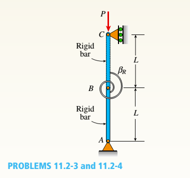
Chapter 11, Problem 11.2.4P
Repeat Problem 11.2-3 assuming that
Expert Solution & Answer
Want to see the full answer?
Check out a sample textbook solution
Students have asked these similar questions
A steel rod placed between two walls is an exact fit and is stress-free at 20 degrees Celsius. Find the temperature at which the compressive stress in the rod is 100 MPa. Use α=11.7×10^(-6)/℃ and E=200 GPa
for the question 7.3-8 in the mechanics of materials textbook by Gere & Goodno 9th edition use
σx = 27 MPa, σy = 5.5 MPa and τxy = 10.5 MPa
instead of the given values there to solve the problem
Problem 3. As shown in the Figure below, please determine the internal force in the middle of AB, with
the given data: OA-15 cm, OB-30 cm, OC-60 cm. W=40N, Wo=60N. F=1214N, B-10°, FM=1236 N,
and 8=15%.
Fj
B
FM
W
Wo
4
Chapter 11 Solutions
Mechanics of Materials - With MindTap
Ch. 11 - A rigid bar of length L is supported by a linear...Ch. 11 - The figure shows an idealized structure consisting...Ch. 11 - -2-3. Two rigid bars are connected with a...Ch. 11 - Repeat Problem 11.2-3 assuming that R= 10 kN ·...Ch. 11 - The figure shows an idealized structure consisting...Ch. 11 - An idealized column consists of rigid bar ABCD...Ch. 11 - An idealized column is made up of rigid segments...Ch. 11 - The figure shows an idealized structure consisting...Ch. 11 - The figure shows an idealized structure consisting...Ch. 11 - The figure shows an idealized structure consisting...
Ch. 11 - The figure shows an idealized structure consisting...Ch. 11 - Rigid column ABCD has an elastic support at B with...Ch. 11 - An idealized column is made up of rigid bars ABC...Ch. 11 - An idealized column is composed of rigid bars ABC...Ch. 11 - Repeat Problem 11.2-14 using L = 12 ft, ß = 0.25...Ch. 11 - An idealized column is composed of rigid bars ABC...Ch. 11 - Column AB has a pin support at A,a roller support...Ch. 11 - Slender column ABC is supported at A and C and is...Ch. 11 - Calculate the critical load PCTfor a W 8 × 35...Ch. 11 - Solve the preceding problem for a W 250 × 89 steel...Ch. 11 - Solve Problem 11.3-3 for a W 10 × 45 steel column...Ch. 11 - A horizontal beam AB is pin-supported at end A and...Ch. 11 - A column ABC is supported at ends A and C and...Ch. 11 - Find the controlling buckling load (kN) for the...Ch. 11 - A column, pinned at top and bottom, is made up of...Ch. 11 - Repeat Problem 11.3-9. Use two C 150 × 12.2 steel...Ch. 11 - A horizontal beam AB is pin-supported at end A and...Ch. 11 - -12 A horizontal beam AB is supported at end A and...Ch. 11 - A horizontal beam AB has a sliding support at end...Ch. 11 - A slender bar AB with pinned ends and length L is...Ch. 11 - A rectangular column with cross-sectional...Ch. 11 - .16 Three identical, solid circular rods, each of...Ch. 11 - Three pinned-end columns of the same material have...Ch. 11 - A long slender column ABC is pinned at ends A and...Ch. 11 - The roof over a concourse at an airport is...Ch. 11 - The hoisting arrangement for lifting a large pipe...Ch. 11 - A pinned-end strut of aluminum (E = 10,400 ksi)...Ch. 11 - The cross section of a column built up of two...Ch. 11 - The truss ABC shown in the figure supports a...Ch. 11 - A truss ABC supports a load W at joint B, as shown...Ch. 11 - An S6 × 12.5 steel cantilever beam AB is supported...Ch. 11 - The plane truss shown in the figure supports...Ch. 11 - A space truss is restrained at joints O, A,B, and...Ch. 11 - A fixed-end column with circular cross section is...Ch. 11 - A cantilever aluminum column has a square tube...Ch. 11 - An aluminum pipe column (E = 10,400 ksi) with a...Ch. 11 - Solve the preceding problem for a steel pipe...Ch. 11 - A wide-flange steel column (E = 30 × l06 psi) of...Ch. 11 - Prob. 11.4.6PCh. 11 - The upper end of a WE × 21 wide-flange steel...Ch. 11 - A vertical post AB is embedded in a concrete...Ch. 11 - The horizontal beam ABC shown in the figure is...Ch. 11 - The roof beams of a warehouse are supported by...Ch. 11 - Determine the critical load Pcrand the equation of...Ch. 11 - A fixed-pinned column is a W310 × 21 steel shape...Ch. 11 - Find the Controlling buckling load (kips) for the...Ch. 11 - Prob. 11.4.14PCh. 11 - A rigid L-shaped frame is supported by a steel...Ch. 11 - An aluminum tube AB with a circular cross section...Ch. 11 - The frame ABC consists of two members AB and BC...Ch. 11 - An aluminum bar having a rectangular cross section...Ch. 11 - ‘11.5-2 A steel bar having a square cross section...Ch. 11 - A simply supported slender column is subjected to...Ch. 11 - A brass bar of a length L = 0.4 m is loaded at end...Ch. 11 - Determine the bending moment M in the pinned-end...Ch. 11 - Plot the load-deflection diagram for a pinned-end...Ch. 11 - Solve the preceding problem for a column with e =...Ch. 11 - A wide-flange member (W200 × 22.5) is compressed...Ch. 11 - A wide-f hinge member (W 10 × 30) is compressed by...Ch. 11 - Solve the preceding problem (W 250 × 44.8) if the...Ch. 11 - The column shown in the figure is fixed at the...Ch. 11 - An aluminum box column with a square cross section...Ch. 11 - Solve the preceding problem for an aluminum column...Ch. 11 - A steel post /t if with a hollow circular cross...Ch. 11 - A frame ABCD is constructed of steel wide-flange...Ch. 11 - A steel bar has a square cross section of width b...Ch. 11 - ]11.6-2 A brass bar (E = 100 GPa) with a square...Ch. 11 - A square aluminum bar with pinned ends carries a...Ch. 11 - A pinned-and column of a length L = 2A m is...Ch. 11 - A pinned-end strut of a length L = 5.2 ft is...Ch. 11 - A circular aluminum tube with pinned ends supports...Ch. 11 - A steel W 12 × 35 column is pin-supported at the...Ch. 11 - A steel W 310 x 52 column is pin-supported at the...Ch. 11 - A steel column (E = 30 x 103 ksi) with pinned ends...Ch. 11 - A W410 × S5 steel column is compressed by a force...Ch. 11 - A steel column ( E = 30 X 103 ksi) that is fixed...Ch. 11 - AW310 × 74 wide-flange steel column with length L...Ch. 11 - A pinned-end column with a length L = 18 ft is...Ch. 11 - The wide-flange, pinned-end column shown in the...Ch. 11 - A W14 × 53 wide-flange column of a length L = 15...Ch. 11 - A wide-flange column with a bracket is fixed at...Ch. 11 - Determine the allowable axial load Pallowa W 10 X...Ch. 11 - Determine the allowable axial load Pallowfor a W...Ch. 11 - Determine the allowable axial load Pallowfor a W...Ch. 11 - Select a steel wide-flange column of a nominal...Ch. 11 - Prob. 11.9.5PCh. 11 - Select a steel wide-flange column of a nominal...Ch. 11 - Prob. 11.9.7PCh. 11 - Determine the allowable axial load Pallowfor a...Ch. 11 - Determine the allowable axial load Pallowfor a...Ch. 11 - Determine the allowable axial load Pallowfor a...Ch. 11 - -11 Determine the maximum permissible length...Ch. 11 - Determine the maximum permissible length Lmaxfor a...Ch. 11 - A steel pipe column with pinned ends supports an...Ch. 11 - The steel columns used in a college recreation...Ch. 11 - A W8 × 28 steel wide-flange column with pinned...Ch. 11 - Prob. 11.9.16PCh. 11 - Prob. 11.9.17PCh. 11 - Prob. 11.9.18PCh. 11 - Prob. 11.9.19PCh. 11 - Prob. 11.9.20PCh. 11 - Prob. 11.9.21PCh. 11 - An aluminum pipe column (alloy 2014-T6) with...Ch. 11 - Prob. 11.9.23PCh. 11 - Prob. 11.9.24PCh. 11 - Prob. 11.9.25PCh. 11 - Prob. 11.9.26PCh. 11 - Prob. 11.9.27PCh. 11 - Prob. 11.9.28PCh. 11 - Prob. 11.9.29PCh. 11 - Prob. 11.9.30PCh. 11 - A wood column with, a rectangular cross section...Ch. 11 - Prob. 11.9.32PCh. 11 - Prob. 11.9.33PCh. 11 - A square wood column with side dimensions b (see...Ch. 11 - A square wood column with side dimensions b (see...Ch. 11 - Prob. 11.9.36P
Knowledge Booster


Learn more about
Need a deep-dive on the concept behind this application? Look no further. Learn more about this topic, mechanical-engineering and related others by exploring similar questions and additional content below.Similar questions
- A brass cube of 48 mm on each edge is comp ressed in two perpendicular directions by forces P = 160 kN (see figure). (a) Calculate the change ...IV in the volume of the cube and the strain energy U stored in the cube. assuming E = 100 GPa and i’ = 0.34. (b) Repeat part (a) if the cube is made of an alumim um alloy with E = 73 GPa and v = 0.33.arrow_forwardA three-story steel column in a building supports roof and floor loads as shown in the figure. The story height H is 10.5 ft. the cross-sectional area A of the column is 15.5 in2, and the modulus of elasticity E of the steel is 30 × 106 psi. Calculate the strain energy U of the column assuming P1= 40 kips and P2= P3= 60 kips.arrow_forwardAn aluminum rod is hanging from one end. The rod is 1 m long and has a square cross section 20 mm by 20 mm. Find the extension of the rod resulting from its own weight. Take E = 70 GPa and the unit weight = 27 kN/m3.arrow_forward
- A rigid beam is supported by a pin at A and two metallic wires at B and C. Determine the force P that causes the point C to displace downward by 0.1 mm. Given: E (wire B) = 200 Gpa, E (wire C)70 Gpa and both wires have a diameterD =6 mm. Consider a linear elastic behavior.A rigid beam is supported by a pin at A and two metallic wires at B and C. Determine the force P that causes the point C to displace downward by 0.1 mm. Given: E (wire B) = 200 Gpa, E (wire C)70 Gpa and both wires have a diameterD =6 mm. Consider a linear elastic behavior.arrow_forwardE = 150 GPa and I = 39.9(10-6) m¹. (Figure 1) Figure 40 kN-m -6 m- 1 of 1 10 kN-m Barrow_forward6. Three wires are used to support the 150-lb force. The wires AB and AC are made of steel, and wire AD is made of copper. Assume that the three wires have constant cross-sectional area A = 0.0123 in?. For steel wire, a = 8 x 10 in/ (in°F ) and E = 29000 ksi and for copper wire, a = 9.6 x 10 in/ (in°F ) and E = 17000 ksi. Calculate the axial force exerted by the three wires if the temperature is raised by 80°F. Answer: Pu= 10 Ib, Pu= 136 Ib 40 in. 60 in. 45°. -45° 60 in. V150 Ibarrow_forward
- Determine the nodal displacements, the forces in each element, and the reactions. Use the direct stiffness method fir these problem Figure P3-10 20 3 60 kN E = 210 GPa A = 3 × 10*m² 3 m 20 3 m 2.arrow_forwardThere is a gap of δ = 0.05cm between the steel and copper bars seen in the figure. i) When the ambient temperature rises to 200oC, will there be a reaction force in the bearings? ii) If there is a reaction force, calculate the reaction forces RA and RB at points A and B. The cross-sectional area of both bars is equal and 5cm ^ 2. Materials;Modules of Elasticity: E Steel = 210 GPa E Copper = 120 GPa Expansion Coefficients: α Steel = 12.10-6 1 / 0C α Copper = 16.10-6 1 / 0Carrow_forwardThe bronze bar 3 m long with a cross-sectional area of 350 mm^2 is placed between two rigid walls. At a temperature of -20 ℃, there is a gap ∆=2.2 mm, as shown in the figure. Find the temperature at which the compressive stress in the bar will be 30 MPa. Use α = (18 x 10^-6)/℃ and E = 80 GPaarrow_forward
- A rigid beam is supported by a pin at A and two metallic wires at B and C. Determine the force P that causes the point C to displace downward by 0.3 mm. Given: E (wire B) = 200 Gpa, E (wire C) = 70 Gpa and both wires have a diameter D=4 mm. Consider a linear elastic behavior. 2 m 1.5 m 3 m 2 m 2 m Select one: O P= 235 N OP= 294 N O P= 471 N P=157 Narrow_forwardThe bronze bar 3.43 m long with a cross-sectional area of 564 mm2 is placed between two rigid walls. At a temperature of 0 °C, there is a gap Δ = 2.24 mm, as shown in the figure. Find the temperature at which the compressive stress in the bar will be 30.69 MPa. Use α = 18 × 10-6 /°C and E = 84.89 GPa.arrow_forwardM y A 2L - 30% В Calculate the support reaction at the roller at A to the nearest whole number. Use up and to the right as positive, down and to the left if negative. M = 63 KN-m P = 143 KN x = 2 y = 7 L = 5 marrow_forward
arrow_back_ios
SEE MORE QUESTIONS
arrow_forward_ios
Recommended textbooks for you
 Mechanics of Materials (MindTap Course List)Mechanical EngineeringISBN:9781337093347Author:Barry J. Goodno, James M. GerePublisher:Cengage Learning
Mechanics of Materials (MindTap Course List)
Mechanical Engineering
ISBN:9781337093347
Author:Barry J. Goodno, James M. Gere
Publisher:Cengage Learning
Stresses Due to Fluctuating Loads Introduction - Design Against Fluctuating Loads - Machine Design 1; Author: Ekeeda;https://www.youtube.com/watch?v=3FBmQXfP_eE;License: Standard Youtube License