Concept explainers
Videos
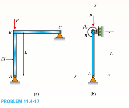
The frame ABC consists of two members AB and BC that are rigidly connected at joint B, as shown in part a of the figure. The frame has pin supports at A and C. A concentrated load P acts at joint B, thereby placing member AB in direct compression.
To assist in determining the buckling load for member AB, represent it as a pinned-end column, as shown in part b of the figure. At the top of the column, a rotational spring of stiffness ßRrepresents the restraining action of the horizontal beam BC on the column (note that the horizontal beam
provides resistance to rotation of joint B when the column buckles). Also, consider only bending effects in the analysis (i.e., disregard the effects of axial deformations).
(a)
By solving the differential equation of the
deflection curve, derive the buckling equation
for this column:
in which L is the length of the column and EI is its flexural rigidity.
(b)
For the particular case when member BC is
identical to member AB, the rotational stiff-
ness ßRequals 3EI/L (see Case 7, Table H-2,Appendix H). For this special case, determine
the critical load Pcr.

Trending nowThis is a popular solution!

Chapter 11 Solutions
Mechanics of Materials - With MindTap


- The plane truss shown in the figure supports vertical loads F at joint D, 2F at joint C, and 3F at joint B. Each member is a slender circular pipe (E = 70 GPa) with an outside diameter of 60 mm and wall thickness of 5 mm. Joint B is restrained against displacement perpendicular to the plane of the truss. Determine the critical value of load variable F(kN) at which member BF fails by Eu1er buckling.arrow_forwardSlender column ABC is supported at A and C and is subjected to axial load P. Lateral support is provided at mid-height if but only in the plane of the figure; lateral support perpendicular to the plane of the figure is provided only at ends A and C. The column is a steel W shape with modulus of elasticity E = 200 GPa and proportional limit pl= 400 MPa. The total length of the column L = 9 m. If the al low-able load is 150 kN and the factor of safety is 2.5, determine the lightest W 200 section that can be used for the column. (See Table F-l(b), Appendix F).arrow_forwardAn idealized column is composed of rigid bars ABC and CD joined by an elastic connection with rotational stiffness ßRIat C. There is a roller support at B and an elastic support at D with translationa1 spring stiffness ß and rotational stiffness ßR2. Find the critical buckling loads for each of the two buckling modes of the column. Assume that L = 3 m, ß = 9 kN/m, and ßR]= ßR1= ßL2. Sketch the buckled mode shapes.arrow_forward
- A truss ABC supports a load W at joint B, as shown in the figure. The length L, of member Aß is fixed, but the length of strut BC varies as the angle is changed. Strut BC has a solid circular cross section. Joint B is restrained against displacement perpendicular to the plane of the truss. Assuming that collapse occurs by Etiler buckling of the strut determine the angle for minimum weight of the strut.arrow_forwardFind expressions for all support reaction Forces in the plane frame with load 3P applied at C as shown in the figure. Joints A and D are pin supported, and there is a roller support at joint F. The lengths and the properties of the members are shown in the figure. Neglect the weights of all members. Select Rfas the redundant.arrow_forwardA rectangular column with cross-sectional dimensions b and h is pin-supported at ends A and C (see figure). At mid-height, the column is restrained in the plane of the figure but is free to deflect perpendicularly to the plane of the figure. Determine the ratio h/b such that the critical load is the same for buckling in the two principal planes of the column.arrow_forward
- A long re Lai nine: wall is braced by wood shores set at an angle of 30° and supported by concrete thrust blocks, as shown in the first part of the figure. The shores are evenly spaced at 3 m apart. For analysis purposes, the wall and shores are idealized as shown in the second part of the figure. Note that the base of the wall and both ends of the shores are assumed to be pinned. The pressure of the soil against the wall is assumed to be triangularly distributed, and the resultant force acting on a 3-meter length of the walls is F = 190 kN. If each shore has a 150 mm X 150 mm square cross section, what is the compressive stressarrow_forwardA long, slender bar in the shape of a right circular cone with length L and base diameter d hangs vertically under the action of its own weight (see figure). The weight of the cone is W and the modulus of elasticity of the material is E. Derive a formula for the increase S in the length of the bar due to its own weight. (Assume that the angle of taper of the cone is small.)arrow_forwardAn idealized column is composed of rigid bars ABC and CD joined by an elastic connection with rotational stiffness ßRat C. There is an elastic support at B with translational spring stiffness ß and a pin support at D. Find the critical buckling loads for each of the two buckling modes of the column in terms of ßL. Assume that ßR= ßL2. Sketch the buckled mode shapes.arrow_forward
- A plane Frame is restrained at joints A and D, as shown in the figure. Members AB and BCD are pin connected at B. A triangularly distributed lateral load with peak intensity of SO N/m acts on CD. An inclined concentrated force of 200 N acts at the mid-span of BC. (a) Find reactions at supports A and D. (b) Find resultant forces in the pins at B and C.arrow_forwardAn idealized column is made up of rigid bars ABC and CD that are joined by a rotational elastic connection at C with stiffness ßR. The column has a roller support at B and a pin support at D. Find an expression for the critical load Pcr of the column.arrow_forwardThe roof over a concourse at an airport is supported by the use of pretensioned cables. At a typical joint in the roof structure, a strut AB is compressed by the action of tensile forces Fin a cable that makes an angle = 75° with the strut (see figure and photo). The strut is a circular tube of steel (E = 30,000 ksi) with outer diameter d2= 2.5 in. and inner diameter d1= 2.0 in. The strut is 5.75 ft long and is assumed to be pin-connected at both ends. Using a factor of safety n = 2.5 with respect to the critical load, determine the allowable force F in the cable.arrow_forward
 Mechanics of Materials (MindTap Course List)Mechanical EngineeringISBN:9781337093347Author:Barry J. Goodno, James M. GerePublisher:Cengage Learning