
Concept explainers
Videos
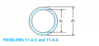
An aluminum pipe column (E = 10,400 ksi) with a length L = 10.0 ft has inside and outside diameters d1= 5.0 in. and d2= 6.0 in., respectively (sec figure). The column is supported only at the ends and may buckle in any direction.
Calculate the critical load Pcrfor the following end conditions: (a) pinned-pinned, (b) fixed-free, (c) fixed-pinned, and (d) fixed-fixed.
i.
The critical load for the pinned-pinned end condition.
Answer to Problem 11.4.3P
The critical load for the pinned-pinned condition is 235 ksi
Explanation of Solution
Given:
E=10400 ksi
L= 10 ft
d1= 5 in
d2= 6 in
Concept Used:
Calculation:
Conclusion:
The critical load for the pinned-pinned condition is 235 ksi
ii.
The critical load for the fixed-free end condition.
Answer to Problem 11.4.3P
The critical load for the fixed-free end condition is 58.75 ksi
Explanation of Solution
Given:
E=10400 ksi
L= 10 ft
d1= 5 in
d2= 6 in
Concept Used:
Calculation:
Conclusion:
The critical load for the fixed-free end condition is 58.75 ksi
iii.
The critical load for the fixed-pinned end condition.
Answer to Problem 11.4.3P
The critical load for the fixed-pinned end condition is 480.96 ksi
Explanation of Solution
Given:
E=10400 ksi
L= 10 ft
d1= 5 in
d2= 6 in
Concept Used:
Calculation:
Conclusion:
The critical load for the fixed-pinned end condition is 480.96 ksi
iv.
The critical load for the fixed-fixed end condition.
Answer to Problem 11.4.3P
The critical load for the fixed-fixed end condition is 940 ksi
Explanation of Solution
Given:
E=10400 ksi
L= 10 ft
d1= 5 in
d2= 6 in
Concept Used:
Calculation:
Conclusion:
The critical load for the fixed-fixed end condition is 940 ksi
Want to see more full solutions like this?
Chapter 11 Solutions
Bundle: Mechanics Of Materials, Loose-leaf Version, 9th + Mindtap Engineering, 1 Term (6 Months) Printed Access Card


- An idealized column is composed of rigid bars ABC and CD joined by an elastic connection with rotational stiffness ßRIat C. There is a roller support at B and an elastic support at D with translationa1 spring stiffness ß and rotational stiffness ßR2. Find the critical buckling loads for each of the two buckling modes of the column. Assume that L = 3 m, ß = 9 kN/m, and ßR]= ßR1= ßL2. Sketch the buckled mode shapes.arrow_forwardA pinned-end strut of aluminum (E = 10,400 ksi) with a length L = 6 ft is constructed of circular tubing with an outside diameter d = 1 in. (sec figure). The strut must resist an axial load F = 4 kips with a factor of safety n = 2.0 with respect to the critical load. Determine the required thickness t of the tube.arrow_forwardAn idealized column is made up of rigid bars ABC and CD that are joined by a rotational elastic connection at C with stiffness ßR. The column has a roller support at B and a pin support at D. Find an expression for the critical load Pcr of the column.arrow_forward
- The figure shows an idealized structure consisting of two rigid bars with pinned connections and linearly elastic rotational springs. Rotational stiffness is denoted ßR. Determine the critical load Pcrfor the structure.arrow_forwardA rigid L-shaped frame is supported by a steel pipe column AB (sec figure) and is subjected to a horizontal load F = 140 kips. If the pipe has an outside diameter d = 4 in. and a factor of safety of 2.5 is required with respect to Euler buckling, what is the minimum acceptable thickness f of the pipe? Assume that E = 30,000 ksi for AB.arrow_forwardAn idealized column is made up of rigid segments ABC and CD that are joined by an elastic connection at C with rotational stiffness ßR= 100 kip-in./rad. The column has a roller support at B and a sliding support at D. Calculate the critical load Pcrof the column.arrow_forward
- A long slender column ABC is pinned at ends A and C and compressed by an axial force F (sec figure). At the midpoint B, lateral support is provided to prevent deflection in the plane of the figure. The column is a steel wide-flange section (W 250 × 67) with E = 200 GPa. The distance between lateral supports is L = 5.5 m. Calculate the allowable load P using a factor of safety n = 2.4, taking into account the possibility of Eu 1er buckling about cither principal centroidal axis (i.e., axis 1-1 or axis 2-2).arrow_forwardA sign for an automobile service station is supported by two aluminum poles of hollow circular cross section, as shown in the figure. The poles are being designed to resist a wind pressure of 75 lb/ft" against the full area of the sign. The dimensions of the poles and sign are hx= 20 ft, /r =5 ft, and h = 10 ft. To prevent buckling of the walls of the poles, the thickness e is specified as one-tenth the outside diameter d. (a) Determine the minimum required diameter of the poles based upon an allowable bending stress of 7500 psi in the aluminum. (b) Determine the minimum required diameter based upon an allowable shear stress of 300 psi.arrow_forwardA flat bar of width b and thickness t has a hole of diameter d drilled through it (see figure). The hole may have any diameter that will fit within the bar. What is the maximum permissible tensile load Pmaxif the allowable tensile stress in the material is st?arrow_forward
- A pinned-and column of a length L = 2A m is constructed of steel pipe (E = 210GPa) having an inside diameter d1= 60 mm and outside diameter d2= 68 mm (sec figure). A compressive load p = 10 kN acts with eccentricity e = 30 mm. What is the maximum compressive stress max in the column? If the allowable stress in the steel is 50 MPa, what is the maximum permissible length Lmaxof the column?arrow_forwardAn idealized column is composed of rigid bars ABC and CD joined by an elastic connection with rotational stiffness ßRat C. There is an elastic support at B with translational spring stiffness ß and a pin support at D. Find the critical buckling loads for each of the two buckling modes of the column in terms of ßL. Assume that ßR= ßL2. Sketch the buckled mode shapes.arrow_forwardA rigid bar of weight W = 750 lb hangs from three equally spaced wires: two of steel and one of aluminum (see figure). The diameter of the wires is 1/8 in. Before they were loaded, all three wires had the same length. What temperature increase T in all three wires will result in the entire load being carried by the steel wires? (Assume Es= 30 × 106 psi, as= 6.5 × 10⁻⁶ /'F, and aa= 12 × 10-6F.)arrow_forward
 Mechanics of Materials (MindTap Course List)Mechanical EngineeringISBN:9781337093347Author:Barry J. Goodno, James M. GerePublisher:Cengage Learning