
Concept explainers
Videos
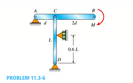
A horizontal beam AB is pin-supported at end A and carries a clockwise moment M at joint B, as shown in the figure. The beam is also supported at C by a pinned-end column of length L: the column is restrained laterally at 0.6Z, from the base at D. Assume the column can only buckle in the plane of the frame. The column is a solid steel bar (E = 200 GPa) of square cross section having length L = 2.4 m and side dimensions h = 70 mm. Let dimensions d = LI2. Based upon the critical load of the column, determine the allowable moment M if the factor of safety with respect to buckling is n = 2.0.

Trending nowThis is a popular solution!

Chapter 11 Solutions
Bundle: Mechanics Of Materials, Loose-leaf Version, 9th + Mindtap Engineering, 1 Term (6 Months) Printed Access Card


- Segments AB and BCD of beam ABCD are pin connected at x = 10 ft. The beam is supported by a pin support at A and roller supports at C and D; the roller at D is rotated by 30* from the x axis (see figure). A trapezoidal distributed load on BC varies in intensity from 5 lb/ft at B to 2.5 lb/ft at C. A concentrated moment is applied at joint A, and a 40-lb inclined load is applied at the mid-span or CD. (a) Find reactions at supports A, C, and D. (b) Find the resultant force in the pin connection at B. (c) Repeat parts (a) and (b) if a rotational spring(kr= 50 ft-lb/radian ) is added at A and the roller at C is removed.arrow_forwardA T-frame structure is composed of prismatic beam ABC and nonprismatic column DBF that are joined at B by a friction less pin connection. The beam has a sliding, support at A and the column is pin supported at F (see figure). Beam ABC and. column segment DB have cross-sectional area A; column segment BF has area 2A. The modulus of elasticity E is the same for both members. Load 2P is applied downward at C, and load P acts at D. Find expressions for the downward displacements of column DBF at D (5D) and also at B (arrow_forwardTwo pipe columns (AB, FC) are pin-connected to a rigid beam (BCD), as shown in the figure. Each pipe column has a modulus of E, but heights (L1or L2) and outer diameters (d1or different for each column. Assume the inner diameter of each column is 3/4 of outer diameter. Uniformly distributed downward load q = 2PIL is applied over a distance of 3L/4 along BC, and concentrated load PIA is applied downward at D. (a) Derive a formula for the displacementarrow_forward
- Beam A BCD has a sliding support at A, roller supports at C and A and a pin connection at B (see figure). Assume that the beam has a rectangular cross section (b = 4 in., h = 12 in.). Uniform load q acts on ABC and a concentrated moment is applied at D. Let load variable q = 1750 lb/ft, and assume that dimension variable L = 4 ft. First, use statics to confirm the reaction moment at A and the reaction forces at Cand A as given in the figure. Then find the ratio of the magnitudes of the principal stresses (crj/os) just left of support Cat a distance d = 8 in. up from the bottom,arrow_forwardBeam A BCD has a sliding support at A, roller supports at C and A and a pin connection at B (see figure). Assume that the beam has a rectangular cross section (b = 4 in., h = 12 in.). Uniform load q acts on ABC and a concentrated moment is applied at D. Let load variable q = 1750 lb/ft, and assume that dimension variable L = 4 ft. First, use statics to confirm the reaction moment at A and the reaction forces at C and A as given in the figure. Then find the ratio of the magnitudes of the principal stresses (crj/os) just left of support Cat a distance d = 8 in. up from the bottom, The pedal and crank are in a horizontal plane and points A and B are located on the top of the crank. The load P = 160 lb acts in the vertical direction and the distances (in the horizontal plane) between the line of action of the load and points A and B are b\ = 5.0 in., h-, = 2.5 in., and/>3 = 1.0 in. Assume that the crank has a solid circular cross section with diameter d = 0.6 inarrow_forwardA flat brass bar has length L, constant thickness t, and a rectangular cross section whose width varies linearly between b2at the fixed support to b1at the free end (see figure). Assume that the taper of the bar is small. The bar has modulus of elasticity E. Calculate the displacements ??Band ??cif P = 200 kN, L = 2 m, t = 20 mm, b, = 100 mm, b, = 115 mm, and E = 96 GPa.arrow_forward
- An L-shaped reinforced concrete slab 12 Ft X 12 ft, with a 6 Ft X 6 ft cut-out and thickness t = 9.0 in, is lifted by three cables attached at O, B, and D, as shown in the figure. The cables are are combined at point Q, which is 7.0 Ft above the top of the slab and directly above the center of mass at C. Each cable has an effective cross-sectional area of Ae= 0.12 in2. (a) Find the tensile force Tr(i = 1, 2, 3) in each cable due to the weight W of the concrete slab (ignore weight of cables). (b) Find the average stress ov in each cable. (See Table I-1 in Appendix I for the weight density of reinforced concrete.) (c) Add cable AQ so that OQA is one continuous cable, with each segment having Force T, which is connected to cables BQ and DQ at point Q. Repeat parts (a) and (b). Hini: There are now three Forced equilibrium equations and one constrain equation, T1= T4.arrow_forwardA column ABC is supported at ends A and C and compressed by an axial load P (figure a). Lateral support is provided at point B but only in the plane of the figure; lateral support perpendicular to the plane of the figure is provided only at A and C. The column is constructed of two channel sections (C 6 × 8.2) back to back (see figure b). The modulus of elasticity of the column is E = 29,500 ksi and the proportional limit is 50 ksi. The height of the column is L = 15 ft. Find the allowable value of load P using a factor of safety of 2.5.arrow_forwardThe roof over a concourse at an airport is supported by the use of pretensioned cables. At a typical joint in the roof structure, a strut AB is compressed by the action of tensile forces Fin a cable that makes an angle = 75° with the strut (see figure and photo). The strut is a circular tube of steel (E = 30,000 ksi) with outer diameter d2= 2.5 in. and inner diameter d1= 2.0 in. The strut is 5.75 ft long and is assumed to be pin-connected at both ends. Using a factor of safety n = 2.5 with respect to the critical load, determine the allowable force F in the cable.arrow_forward
- Solve the preceding problem for a steel pipe column (E = 210 GPa) with length L = 1.2 m, inner diameter d2= 36 mm, and outer diameter d2=40 mm.arrow_forwardThe horizontal beam ABC shown in the figure is supported by columns BD and CE. The beam is prevented from moving horizontally by the pin support at end A. Each column is pinned at its upper end to the beam, but at the lower ends, support D is a sliding support and support E is pinned. Both co lu in us arc solid steel bars (E = 30 × 106 psi) of square cross section with width equal to 0.625 in. A load Q acts at distance a from column BD. If the distance a = 12 in., what is the critical value Qcr of the load? If the distance a can be varied between 0 and 40 in., what is the maximum possible value of Qcr? What is the corresponding value of the distance a?arrow_forwardA solid steel bar of diameter d1= 1.50 in. is enclosed by a steel tube of outer diameter d3= 2.25 in, and inner diameter d2= 1,75 in. (see figure). Both bar and tube arc held rigidly by a support at end A and joined securely to a rigid plate at end B. The composite bar, which has length L = 30.0 in., is twisted by a torque T = 5000 lb-in, acting on the end plate. Determine the maximum shear stresses r, and r2in the bar and tube, respectively. Determine the angle of rotation 0 (in degrees) of the end plate, assuming that the shear modulus of the steel is G = 116 × 106 psi. Determine the torsional stiffness kTof the composite bar.arrow_forward
 Mechanics of Materials (MindTap Course List)Mechanical EngineeringISBN:9781337093347Author:Barry J. Goodno, James M. GerePublisher:Cengage Learning