
System Dynamics
3rd Edition
ISBN: 9780073398068
Author: III William J. Palm
Publisher: MCG
expand_more
expand_more
format_list_bulleted
Videos
Textbook Question
Chapter 11, Problem 11.8P
PID control action is applied to the plant
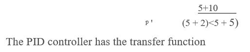
GPU) =
Ge(j) = Kp f 1 + y— +
Use the values Ti = 0.2 and To = 0.5. Plot the root locus with the proportional gain Kp as the parameter.
Expert Solution & Answer
Want to see the full answer?
Check out a sample textbook solution
Students have asked these similar questions
Q.1 - The open loop transfer function for a unity - feedback systemis G(s)= XL‘ 7xs and r(t)=3t determine steady state error.If it is desired to reduce this existing error by 7% fined new value of gain of the system.
1.block diagram physical meaning and the time response for different inputs
a)is the aircraft stable about the equilibrium represented by the transfer function?
b) Using proportional feedback,what is the range of acceptable gains for the closed loop systen to be stable?
c) Design a feedback control system that allows the pilot to command a pitch angle with overshoot less than or equal to 4.15% and a natural frequency of greater than or equal to 0.99 rad/s
d) Design a feedback control system that allows the pilot to command a pitch angle with the same overshoot and a natural frequency of one half the system in part c.
Chapter 11 Solutions
System Dynamics
Ch. 11 - Prob. 11.1PCh. 11 - Prob. 11.2PCh. 11 - Prob. 11.3PCh. 11 - Sketch the root locus plot of ms~ 4- 12s + 10 = 0...Ch. 11 - Prob. 11.5PCh. 11 - Prob. 11.6PCh. 11 - Prob. 11.7PCh. 11 - PID control action is applied to the plant GPU) =...Ch. 11 - Consider the following equation where the...Ch. 11 - 11.10 In the following equation. K > 0.
j2(j+9) +...
Ch. 11 - 11.11 Consider the following equation where the...Ch. 11 - 11.12 In the following equations, identify the...Ch. 11 - Prob. 11.13PCh. 11 - Prob. 11.14PCh. 11 - Prob. 11.15PCh. 11 - Prob. 11.16PCh. 11 - Prob. 11.17PCh. 11 - Prob. 11.18PCh. 11 - Prob. 11.19PCh. 11 - Prob. 11.20PCh. 11 - Prob. 11.21PCh. 11 - Prob. 11.23PCh. 11 - Prob. 11.24PCh. 11 - Prob. 11.25PCh. 11 - Prob. 11.26PCh. 11 - Prob. 11.27PCh. 11 - Prob. 11.28PCh. 11 - Prob. 11.29PCh. 11 - Prob. 11.30PCh. 11 - Prob. 11.32PCh. 11 - Prob. 11.33PCh. 11 - Prob. 11.34PCh. 11 - Prob. 11.35PCh. 11 - The following equations are the model of the roll...Ch. 11 - Prob. 11.38P
Knowledge Booster


Learn more about
Need a deep-dive on the concept behind this application? Look no further. Learn more about this topic, mechanical-engineering and related others by exploring similar questions and additional content below.Similar questions
- Name two effects of negative feedback.arrow_forwardCalculating the separation and / or joining angles in the negative feedback control circuit, if any, given as Controlling (K) and Controlled G (s) = (s + 1) / (s2-4 * s + 5) Explanation: The roots of the equation (s2-4 * s + 5); s1 = 2 + 1 * j and s2 = 2-1 * j and the system Transfer Function is TF (s) = K * G (s) / (1 + K * G (s)). a. There are split angles up to (+108.435) and (-108.435) b. There are split angles as much as (+71,565) and (-71,565) c. There are conjunction angles of (+90) and (-90). D. There are separation angles as much as (+18.435) and (-18.435). E. There are no separation and convergence angles.arrow_forward1. Give an example of open loop and closed loop system (one example each). Also state the input, control system, feedback and output parameter. Example. 1. Open Loop - Water Heater: Input - Water Temperature (Cold) System - Heating Element Output - Water Temperature (Hot) 2. Closed Loop - Air-conditioning System Input - Desired Room Temperature Control - Motor controller/Compressor/ACU Feedback - Temperature Sensing Output - Room Temperaturearrow_forward
- 18- A)Define the following(i) Sensitivity (ii) Transfer function of closed loop control systemarrow_forwardPLEASE GIVE COMPLETE AND DETAILED SOLUTION The oven shown in Figure 1 has a heating element, qi with capacitances C = 50 J/K. The corresponding temperature is T and ambient temperature is Ta. The thermal resistance of the oven wall is R = 2 K-s/J. The system has a steady-state error in the response, T(t) to a change in the reference input. The steady state error can be reduced if a proportional control action, Kp is included in the controller. Determine the range of values of Kp of the system so that the steady state error is lower than 0.4. (Hint: Kindly determine the steady state error at value 0.4)arrow_forwardfind trasfer function Y(s)/R(s) if kc is 5 and plant is 1/(0.5s+1). input r(t) is a unit-step functionarrow_forward
- 10- The laplace transform of output variable to laplace transform of input variable is called as control system. Select one: True Falsearrow_forwardneed in s domainarrow_forwardFigure 1 shows an electrical system comprising a series RLC circuit and input voltagesource ein(t).(a) Derive the input-output equation with output y = I and input u = ein(t). (b) Using the derived input-output equation, drive the system transfer function G(s)that relates output to input. Use the following numerical values for the electrical systemparameters: resistance R = 2Ω, inductance L = 0.25H, and capacitance C = 0.4F. (c) Using the derived transfer function, derive the time-domain ordinary differentialequation for the input-output equation of this electrical system. (d) Draw the complete block diagram of this series RLC circuit using the derived transferfunction.arrow_forward
- A proportional controller is used to control the height of water in a tank where the water level can vary from 0 to 4.0 m. The required height of water is and the controller is to close a valve fully when the water rises to 3.9 and open it fully when the water falls to 3.1 m. What transfer function will be required? source : Mechatronics: Electronic Control Systems in Mechanical and Electrical Engineering 6th Edition by W. Bolton question 22.4arrow_forwardBased on the pic attached, If component B of #6 is changed to 3 parallel components and each has thesame reliability, what is the system reliability now? pls provide celaar solutions detailed thanksarrow_forwardA stock-flow system models the level of water in a lake. Near a certain equilibrium point, there are three feedback loops: an amplifying feedback loop with strength of +0.55 per month, a stabilizing feedback loop with strength of -0.09 per month, and an amplifying feedback loop with strength of +0.79 per month. Calculate the strength of the overall feedback.arrow_forward
arrow_back_ios
SEE MORE QUESTIONS
arrow_forward_ios
Recommended textbooks for you
 Principles of Heat Transfer (Activate Learning wi...Mechanical EngineeringISBN:9781305387102Author:Kreith, Frank; Manglik, Raj M.Publisher:Cengage Learning
 Understanding Motor ControlsMechanical EngineeringISBN:9781337798686Author:Stephen L. HermanPublisher:Delmar Cengage Learning
Principles of Heat Transfer (Activate Learning wi...
Mechanical Engineering
ISBN:9781305387102
Author:Kreith, Frank; Manglik, Raj M.
Publisher:Cengage Learning
Understanding Motor Controls
Mechanical Engineering
ISBN:9781337798686
Author:Stephen L. Herman
Publisher:Delmar Cengage Learning
Quality Control and Quality Assurance; Author: AISC Education;https://www.youtube.com/watch?v=C2PFj9YZ_mw;License: Standard Youtube License