
Connect 1-semester Access Card For Shigley's Mechanical Engineering Design
10th Edition
ISBN: 9780077591632
Author: Richard G Budynas; Keith J Nisbett
Publisher: McGraw-Hill Education
expand_more
expand_more
format_list_bulleted
Concept explainers
Videos
Textbook Question
Chapter 11, Problem 31P
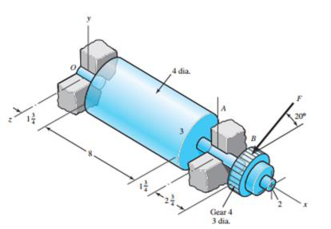
Shown in the figure is a gear-driven squeeze roll that mates with an idler roll. The roll is designed to exert a normal force of 35 lbf/in of roll length and a pull of 28 lbf/in on the material being processed. The roll speed is 350 rev/min, and a design life of 35 kh is desired. Use an application factor of 1.2, and select a pair of angular-contact 02-series ball bearings from Table 11-2 to be mounted at 0 and A. Use the same size bearings at both locations and a combined reliability of at least 0.92, assuming distribution data from manufacturer 2 in Table 11-6.
Expert Solution & Answer
Want to see the full answer?
Check out a sample textbook solution
Students have asked these similar questions
A truck equipped with a 50 HP engine uses a roller chain as the final drive to the rear
axle. The driving sprocket runs at 225 rpm with a center distance of approximately 500
fpm. The transmission efficiency between the engine and the driving sprocket is 85%.
1.1 Determine the pitch and width of chain to be used.
1.2 Determine the number of teeth in each sprocket and the pitch diameters.
3.A chain drive using bush roller chain transmits 5.6 kW of power. The driving shaft on an electric motor runs at 1440 r.p.m. and velocity ratio is 5. The centre distance of the drive is restricted to 550 ± 2% mm and allowable pressure on the pivot joint is not to exceed 10 N/mm2. The drive is required to operate continuously with periodic lubrication and driven machine is such that load can be regarded as fairly constant with jerk and impact. Design the chain drive by calculating leading dimensions, number of teeth on the sprocket and specify the breaking strength of the chain. Assume a factor of
A 15 kW and 1200 r.p.m. motor drives a compressor at 300
r.p.m. through a pair of spur gears having
20° stub teeth. The centre to centre distance between the shafts
is 400 mm. The motor pinion is made
of forged steel having an allowable static stress as 210 MPa,
while the gear is made of cast steel
having allowable static stress as 140 MPa. Assuming that the
drive operates 8 to 10 hours per day
under light shock conditions, find from the standpoint of
strength,
1. Module; 2. Face width and 3. Number of teeth and pitch circle
diameter of each gear.
Check the gears thus designed from the consideration of wear.
The surface endurance limit may be
taken as 700 MPa
Chapter 11 Solutions
Connect 1-semester Access Card For Shigley's Mechanical Engineering Design
Ch. 11 - Manufacturer Rating Life, Revolutions Weibull...Ch. 11 - Manufacturer Rating Life, Revolutions Weibull...Ch. 11 - Manufacturer Rating Life, Revolutions Weibull...Ch. 11 - Problems 112 and 113 raise the question of the...Ch. 11 - Prob. 5PCh. 11 - Manufacturer Rating Life, Revolutions Weibull...Ch. 11 - Two ball bearings from different manufacturers are...Ch. 11 - 11-8 to 11-13 For the bearing application...Ch. 11 - 11-8 to 11-13 For the bearing application...Ch. 11 - 11-8 to 11-13 For the bearing application...
Ch. 11 - 11-8 to 11-13 For the bearing application...Ch. 11 - 11-8 to 11-13 For the bearing application...Ch. 11 - 11-8 to 11-13 For the bearing application...Ch. 11 - A countershaft carrying two V-belt pulleys is...Ch. 11 - A countershaft carrying two V-belt pulleys is...Ch. 11 - A countershaft carrying two V-belt pulleys is...Ch. 11 - A countershaft carrying two V-belt pulleys is...Ch. 11 - For the shaft application defined in Prob. 3-77,...Ch. 11 - For the shaft application defined in Prob. 3-79,...Ch. 11 - An 02-series single-row deep-groove ball bearing...Ch. 11 - An 02-series single-row deep-groove ball bearing...Ch. 11 - 11-22 to 11-26 An 02-series single-row deep-groove...Ch. 11 - 1122 to 1126 An 02-series single-row deep-groove...Ch. 11 - 1122 to 1126 An 02-series single-row deep-groove...Ch. 11 - 1122 to 1126 An 02-series single-row deep-groove...Ch. 11 - 1122 to 1126 An 02-series single-row deep-groove...Ch. 11 - The shaft shown in the figure is proposed as a...Ch. 11 - Repeat the requirements of Prob. 11-27 for the...Ch. 11 - The shaft shown in the figure is proposed as a...Ch. 11 - Repeat the requirements of Prob. 11-29 for the...Ch. 11 - Shown in the figure is a gear-driven squeeze roll...Ch. 11 - The figure shown is a geared countershaft with an...Ch. 11 - The figure is a schematic drawing of a...Ch. 11 - A gear-reduction unit uses the countershaft...Ch. 11 - The worm shaft shown in part a of the figure...Ch. 11 - In bearings tested at 2000 rev/min with a steady...Ch. 11 - A 16-tooth pinion drives the double-reduction...Ch. 11 - Estimate the remaining life in revolutions of an...Ch. 11 - The same 02-30 angular-contact ball bearing as in...Ch. 11 - A countershaft is supported by two tapered roller...Ch. 11 - For the shaft application defined in Prob. 3-74,...Ch. 11 - For the shaft application defined in Prob. 3-76,...Ch. 11 - Prob. 43PCh. 11 - The gear-reduction unit shown has a gear that is...
Knowledge Booster


Learn more about
Need a deep-dive on the concept behind this application? Look no further. Learn more about this topic, mechanical-engineering and related others by exploring similar questions and additional content below.Similar questions
- A 15 kW and 1200 r.p.m. motor drives a compressor at 300 r.p.m. through a pair of spur gears having 20° stub teeth. The centre to centre distance between the shafts is 400 mm. The motor pinion is made of forged steel having an allowable static stress as 210 MPa, while the gear is made of cast steel having allowable static stress as 140 MPa. Assuming that the drive operates 8 to 10 hours per day under light shock conditions, find from the standpoint of strength, 1. Module; 2. Face width and 3. Number of teeth and pitch circle diameter of each gear. Check the gears thus designed from the consideration of wear. The surface endurance limit may be taken as 700 MParrow_forwardA cylinder with a nominal 2.5 in ID, a 4.0 in OD, and a 3.0 in length is to be mated with a solid shaft with a nominal 2.5 in diameter. A medium drive fit is desired (as defined in Table 7-9). The cylinder and shaft are made from steel, with Sy = 100 kpsi and E = 30 Mpsi. The coefficient of friction for the steel interface is 0.7. a. Specify the maximum and minimum allowable diameters for both the cylinder hole and the shaft. b. Determine the torque that can be transmitted through this joint, assuming the shaft and cylinder are both manufactured within their tolerances such that the minimum interference is achieved. c. Suppose the shaft and cylinder are both manufactured within their tolerances such that the maximum interference is achieved. Check for yielding of the cylinder at its inner radius by finding the following: i. The pressure at the interface ii. The tangential and radial stresses in the cylinder, at its inner radius. iii. The factor of safety for static yielding of the…arrow_forwardA steel shaft 800 mm long transmitting 15 kW at 400 r.p.m. is supported at two bearings at the twoends. A gear wheel having 80 teeth and 500 mm pitch circle diameter is mounted at 200 mm from theleft hand side bearing and receives power from a pinion meshing with it. The axis of pinion and gearlie in the horizontal plane. A pulley of 300 mm diameter is mounted at 200 mm from right hand sidebearing and is used for transmitting power by a belt. The belt drive is inclined at 30° to the vertical inthe forward direction. The belt lap angle is 180 degrees. The coefficient of friction between belt andpulley is 0.3. Design and sketch the arrangement of the shaft assuming the values of safe stresses as :τ = 55 MPa; σt= 80 MPa. Take torsion and bending factor 1.5 and 2 respectively.arrow_forward
- A single trapezoidal metric thread power screw is to raise a load of 60 kN. The screw has a mean diameter of 34 mm and a pitch of 5 mm. The coefficient of thread friction and collar friction are 0.15 and 0.11, respectively. The collar mean diameter is 90 mm and the screw turns at 150 rpm. Determine the total torque required to raise the load in N-m.arrow_forwardA single deep grove ball bearing series 3, the outer ring rotates at 1500 rpm with little shock load. Bearing has a bore diameter of 45 mm, working with a load 1890 lb radial and 1250 lb axial load. Determine the rated life and median life of the bearing. Use the design factors according to the attached table.arrow_forwardA chain drive using bush roller chain transmits 5.6 kW of power. The driving shaft on an electric motor runs at 1440 r.p.m. and velocity ratio is 5. The centre distance of the drive is restricted to 550 ± 2% mm and allowable pressure on the pivot joint is not to exceed 10 N/mm2. The drive is required to operate continuously with periodic lubrication and driven machine is such that load can be regarded as fairly constant with jerk and impact. Design the chain drive by calculating leading dimensions, number of teeth on the sprocket and specify the breaking strength of the chain. Assume a factor of safety of 13.arrow_forward
- A pair of helical gears transmit 15 KW power and the pinion is rotating at 1000 rpm. The helix angle is 0.50 radians and the normal pressure angle is 0.35 radians. The pitch diameter of the pinion is 70 mm and the pitch diameter of the gear is 210 mm. Determine the tangential, radial, and axial forces between the gear teeth.arrow_forwardA single stage spur gear gearbox has a module of 1.5mm and an input speed of 1500.p.m. and a pinion with 15 teeth. The overall ratio of the gearbox is 6:1 and the gearbox is transmitting a power of 6000W. If the factor of safetv is to be reduced to an absolute minimum acceptable value and the gears are to be made from a material with a Yield stress of 540 MPa, what is the face width of the gears (in mm) Express your answer in the form 21.00 ie with two decimal place an no unitsarrow_forwardi) Explain the static rating of rolling contact bearings. ii) Write any three technical reasons why ball and roller bearings need to be lubricated. b) Design a self-aligning ball bearing to be used in a turbine to carry a combined radial load of 4466 N and thrust load of 1420 N. The basic dynamic load rating of the bearing is 31 kN at 547 rpm. Take k=3 for all types of ball bearings. Take the value of the shock load factor as 1.3. The axial and radial load factors are 1.8 and 1.2 respectively and the rotational factor is 1. Calculate: i) Basic equivalent dynamic load in N ii) Design equivalent dynamic load in N iii) Expected life of bearings in hoursarrow_forward
- The reducer input shaft shown in the figure is taperedIt transmits moment with the help of a gear wheel.On the spindle, Fa = 552 N, Fr = 457 N, Ft = 1960 Nfrom gear forces and belt mechanismincoming Fk = 2600 N radial force impact. The shaft rotates with n = 1090 rpm.Accept the shaft diameter in the A bearing as dA = 35 mm.Fixed ball bearing for Lh = 13500 hselectarrow_forwardA 15 kW and 1200 motor drives a compressor at 300 a pair of spur gears having . The center-to-center distance between the shafts is 400 . The motor pinion is made of forged steel having an allowable static stress as 210 MPa, while the gear is made of cast steel having allowable static stress as 140 MPa . Assuming that the drive operates 8 to 10 hours per day under light conditions , find from the standpoint of strength Module , 2. Fare and 3. Number of teeth and pitch circle diameter of each gear 2. Check the gears thus designed from the consideration of Static tooth load or endurance strength of the tooth flexural endurance limil (sigma_{\epsilon}) may be taken as 400 MPa 3. Check the gears thus designed from the consideration of wear surface endurance limit ( sigma epsilon x ) may be taken 700 MPa b ^ pi ( 6.154 - 0512/pi; F_{N}arrow_forward.........A shaft rotating at 150 rpm is subjected to variable load: 8 kN during 60% of the time and 2 kN during 40% of the time. Calculate the basic dynamic load rating in kN for the roller bearing (k = 10/3) for 7200 hours of operation with not more than 10% failures.arrow_forward
arrow_back_ios
SEE MORE QUESTIONS
arrow_forward_ios
Recommended textbooks for you
 Elements Of ElectromagneticsMechanical EngineeringISBN:9780190698614Author:Sadiku, Matthew N. O.Publisher:Oxford University Press
 Mechanics of Materials (10th Edition)Mechanical EngineeringISBN:9780134319650Author:Russell C. HibbelerPublisher:PEARSON
 Thermodynamics: An Engineering ApproachMechanical EngineeringISBN:9781259822674Author:Yunus A. Cengel Dr., Michael A. BolesPublisher:McGraw-Hill Education
 Control Systems EngineeringMechanical EngineeringISBN:9781118170519Author:Norman S. NisePublisher:WILEY
 Mechanics of Materials (MindTap Course List)Mechanical EngineeringISBN:9781337093347Author:Barry J. Goodno, James M. GerePublisher:Cengage Learning
 Engineering Mechanics: StaticsMechanical EngineeringISBN:9781118807330Author:James L. Meriam, L. G. Kraige, J. N. BoltonPublisher:WILEY
Elements Of Electromagnetics
Mechanical Engineering
ISBN:9780190698614
Author:Sadiku, Matthew N. O.
Publisher:Oxford University Press
Mechanics of Materials (10th Edition)
Mechanical Engineering
ISBN:9780134319650
Author:Russell C. Hibbeler
Publisher:PEARSON
Thermodynamics: An Engineering Approach
Mechanical Engineering
ISBN:9781259822674
Author:Yunus A. Cengel Dr., Michael A. Boles
Publisher:McGraw-Hill Education
Control Systems Engineering
Mechanical Engineering
ISBN:9781118170519
Author:Norman S. Nise
Publisher:WILEY
Mechanics of Materials (MindTap Course List)
Mechanical Engineering
ISBN:9781337093347
Author:Barry J. Goodno, James M. Gere
Publisher:Cengage Learning
Engineering Mechanics: Statics
Mechanical Engineering
ISBN:9781118807330
Author:James L. Meriam, L. G. Kraige, J. N. Bolton
Publisher:WILEY
How to Measure Threads; Author: PracticalMachinist;https://www.youtube.com/watch?v=Uuy7EViS7Kc;License: Standard Youtube License