
Concept explainers
Videos
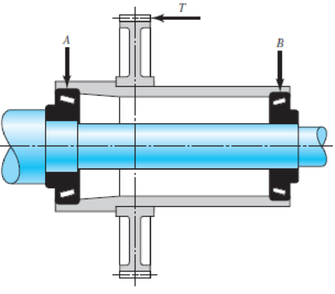
The gear-reduction unit shown has a gear that is press fit onto a cylindrical sleeve that rotates around a stationary shaft. The helical gear transmits an axial thrust load T of 250 lbf as shown in the figure. Tangential and radial loads (not shown) are also transmitted through the gear, producing radial ground reaction forces at the bearings of 875 lbf for bearing A and 625 lbf for bearing B. The desired life for each bearing is 90 kh at a speed of 150 rev/min with a 90 percent reliability. The first iteration of the shaft design indicates approximate diameters of
Problem 11–44
(Courtesy of The Timken Company.)
Want to see the full answer?
Check out a sample textbook solution
Chapter 11 Solutions
Connect 1-semester Access Card For Shigley's Mechanical Engineering Design


- The motor shown in the figure supplies 16.5 kW at 1540 rpm at A. Shafts (1) and (2) are each solid 28 mm diameter shafts. Shaft (1) is made of an aluminum alloy [ G=26 GPa], and shaft (2) is made of bronze [ G=45 GPa]. The shaft lengths are L1=3.3m and L2=2.9m, respectively. Gear B has 56 teeth, and gear C has 97 teeth. The bearings shown permit free rotation of the shafts. Determine: the rotation angle of gear D with respect to flange A. [Answer φD/A = 0.314 rad]arrow_forwardIn the gear system shown in the figure, the motor applies a torque of 231 N-m to the gear at A. A torque of TC = 440 N-m is removed from the shaft at gear C, and the remaining torque is removed at gear D. Segments (1) and (2) are solid 38-mm-diameter steel (G = 80 GPa) shafts, and the bearings shown allow free rotation of the shaft. Assume DA = 110 mm, DB = 370 mm, L1 = 1.7 m, and L2 = 1.1 m. Calculate the rotation angle of gear D relative to gear B. Express your answer in radian rounded to the nearest thousandths.arrow_forwardThe shaft shown in the figure is machined from AISI 1040 CD steel. The shaft rotates at 1600 rpm and is supported in rolling bearings at A and B. The applied forces are F1 = 1600 lbf and F2 = 640 lbf. A steady torque of 1600 lbf·in is being transmitted through the shaft between the points of application of the forces.arrow_forward
- a) A line shaft as shown in Figure Q is driven using a motor placed vertically below it. The pulley on the line shaft is 1.6 m in diameter and has belt tensions 7.5 kN and 2.4 kN on the tight side and slack side of the belt respectively. Both tensions may be assumed to be vertical and the weight of the pulley is negligible. If the pulley is overhang from the shaft, the distance of the centre line of the pulley from the centre line of the bearing being 500 mm.6.Figure Q(i) Predict using distortion energy theory, the appropriate diameter of the shaft that failure will not occur if the yield strength, Sy = 370 Mpa and factor of safety is 2.5. (ii) Assuming the maximum allowable shear stress of 42 MPa, find its diameter using maximum shear stress theory. (iii) Comparing the diameters in (i) and (iii) above, which of them would you have used to design your shaft and why?arrow_forwardA 15KW and 1200r.p.m motor drives a compressor at 300r.p.m through a pair of spur gears having 20° stub teeth .the centre to centre distance between the shafts is 400mm.the motor pinion is made to forged steel having an allowable static stress 210MPa while the gear is made of cast steel having an allowable static stress as 140MPa.Assuming that the drive operates 8 to 10 hours per day under light shock conditions,find from the standpoint of strength (a) Module;(b)face width and (c)number of teeth an pitch circle diameter of each gear.check the gears thus designed from the consideration of wear .the surface endurance limit may be taken as 700MPa.arrow_forwardA straight gear with module m = 5 mm and face width bw = 40 mm has center distance cd = 0.1875m. The pinion has 25 teeth, the speed is 1000 rpm, and pressure angle ᶲ = 200. Find the Hertzian contact stress at the pitch point when the gear transmits 10 kW. Neglect friction forces. The gear steel has modulus of elasticity E = 207 GPa and a Poisson’s ratio of 0.30.arrow_forward
- A compound shaft drives three gears, as shown. Segments (1) and (2) of the compound shaft are hollow bronze [G = 6,500 ksi] tubes, which have an outside diameter of 2.40 in. and a wall thickness of 0.1375 in. Segments (3) and (4) are solid 1.00-in.-diameter steel [G = 11,500 ksi] shafts. The shaft lengths are L1 = 58 in., L2 = 16 in., L3 = 16 in., and L4 = 28 in. The torques applied to the shafts have magnitudes of TB = 970 lb·ft, TD = 430 lb·ft, and TE = 170 lb·ft, acting in the directions shown. The bearings shown allow the shaft to turn freely. Using the sign convention presented in Section 6.6., calculate: (a) the magnitude of the maximum shear stress in the compound shaft. (b) the rotation angle of flange C with respect to flange A. (c) the rotation angle of gear E with respect to flange A.arrow_forwardIn the fabric dye-printing system given in the figure, the motion is transmitted from the electric motor to the drum of the machine. There is a two-stage reducer in between. Number of teeth of gears z1=17; z2=85; z3=18; z4=72; The efficiency of a pair of gears is given as na=0.97 and the efficiency of each of the gearbox shafts and lower bearing pairs to the drum bearing is given as n=0.97. The diameter of the drum will be D=200 mm, the fabric speed will be v=1 m/s and the pulling force required to activate the band will be taken as F-2000 N. a) Find the number of revolutions of the engine. b) Find the required engine power.arrow_forward5. Design a sleeve coupling for the transmission of 12 kW at 300 rpm by two connected steel shafts. Take service factor KS 1.25. The sleeve is made of CI. The key and the shaft are made of the same material. Allowable stress: Shear stresses in key and shaft 50 MPa Crushing stress in key= 100 MPa Shear stress in CI sleeve = 10 MPaarrow_forward
- Write legibly, provide manual step by step solution, and diagram for below given problem. A 2.5 in diameter 10 spline shaft ( d= 0.86D, w= 0.156D, h= 0.07D ) to slide when not under load has a compressive force of 2500 lb. Find the torque applied if hub length is 1 1/2 in. Ans. 2906.25 in-lbarrow_forwardA solid steel shaft with an outsidediameter of 1.5 in. is supported in flexiblebearings at A and C as shown in FigureP15.43/44. Two pulleys are keyed to the shaft atB and D. Pulley B has a diameter of D B = 14 in.and belt tensions of T 1 = 100 lb and T 2 = 220 lb.Pulley D has a diameter of D D = 7 in. and belttensions of T 3 = 60 lb and T 4 = 300 lb. Lengthdimensions of the shaft are x1 = 8 in., x2 = 4 in.,x3 = 3 in., and x4 = 6 in. Determine the normaland shear stresses at point K on the shaft. Showthe orientation of these stresses on anappropriate sketch.FIGURE P15.43/44arrow_forwardA gear reducer similar to Figure 3–1(a), transmits power from input shaft AB to output shaft CD. The input torque and constant speed are T = 200 lbf-in and ωi = 60 rev/min, respectively. The output load torque and speed are To and ωo, respectively. (c) Shaft AB, with diameter 0.5 in, is supported by ball bearings at A and B, which can be treated as simple supports. For this shaft, the dimension from A to gear G1 is 1.5 in, and gear G1 to B is 2 in. The pitch radii of the gears are r1 = 1.0 in and r2 = 2.5 in. For the spur gears, the pressure angle, ϕ, is 20 degrees. The book name is Shigleys Mechanical Engineering design 11tharrow_forward
 Mechanics of Materials (MindTap Course List)Mechanical EngineeringISBN:9781337093347Author:Barry J. Goodno, James M. GerePublisher:Cengage Learning