
Videos
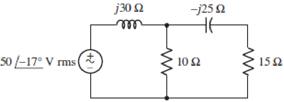
■ FIGURE 11.49
Instead of including a capacitor as indicated in Fig. 11.49, the circuit is erroneously constructed using two identical inductors, each having an impedance of j30 W at the operating frequency of 50 Hz. (a) Compute the complex power delivered to each passive component. (b) Verify your solution by calculating the complex power supplied by the source. (c) At what power factor is the source operating?
(a)
Find the complex power delivered to each passive element when
Answer to Problem 53E
The complex power delivered to
Explanation of Solution
Given data:
Refer to Figure 11.49 in the textbook for the given circuit.
Operating frequency is 50 Hz.
Formula used:
Write the expression for complex power delivered to the element as follows:
Here,
Write the expression for current in terms of voltage and impedance as follows:
Calculation:
Consider
Use the expression in Equation (2) and find the source current as follows:
Substitute
Use voltage division rule and find the voltage across
Substitute
Modify the expression in Equation (1) for the complex power delivered to
Substitute
Consider the node voltage across the shunt branches as
Substitute
Use current division rule and find the current through
Substitute
Modify the expression in Equation (1) for the complex power delivered to the
Substitute
Use voltage division rule and find the voltage across
Substitute
Use current division rule and find the current through
Substitute
Modify the expression in Equation (1) for the complex power delivered to the
Substitute
Use voltage division rule and find the voltage across
Substitute
Modify the expression in Equation (1) for the complex power delivered to the
Substitute
Conclusion:
Thus, the complex power delivered to
(b)
Verify the solution obtained in Part (a) by calculating the complex power supplied by the source.
Explanation of Solution
Calculation:
Modify the expression in Equation (1) for the complex power supplied by the source as follows:
Substitute
Write the expression for sum of complex delivered to (or absorbed by) each passive element as follows:
From Part (a), substitute
From the calculation, it is clear that, the complex power supplied by the source is equal to the complex power delivered to each passive element.
Conclusion:
Thus, the solution obtained in Part (a) is verified.
(c)
Find the power factor of the source.
Answer to Problem 53E
The power factor of the source is 0.253 lagging.
Explanation of Solution
Formula used:
Write the expression for complex power in the rectangular form as follows:
Here,
Write the expression for power factor as follows:
Calculation:
Rewrite the expression for complex power supplied by the source in rectangular form as follows:
Compare the complex power supplied by the source with the expression in Equation (3) and write the average and reactive power supplied by the source as follows:
Substitute 19.1482 W for
If the imaginary part of the complex power (reactive power) is positive value, then the load has lagging power factor. If the imaginary part is negative value, then the load has leading power factor.
As the imaginary part of the given complex power is positive value, the power factor is lagging power factor.
Conclusion:
Thus, the power factor of the source is 0.253 lagging.
Want to see more full solutions like this?
Chapter 11 Solutions
Loose Leaf for Engineering Circuit Analysis Format: Loose-leaf


- A resistor of 50 ohms, a 200mH inductor, and a 1.5 x 10⁻⁴ F capacitor is connected in parallel to a 120-volt, 60 cps source. Calculate: a) the equivalent impedance b) the current in each load c) total current d) the total real, reactive, and apparent powers e) power factor.arrow_forwardA 550-V feeder line supplies an industrial plant consisting of a motor drawing 60 kW at 0.75 pf (inductive), a capacitor with a rating of 20 kVAR, and lighting drawing 10 kW. (a) Calculate the total reactive power and apparent power absorbed by the plant. (b) Determine the overall pf. (c) Find the current in the feeder line.arrow_forwardF.) A residential air conditioning unit with an SEER of 14 serves a single-detached family residence in Quezon City, Philippines having an annual cooling load hours of 6,116 hours. The total cooling load is 36,000 Btu/hr. Calculate the approximate annual energy consumption of the A/C unit.arrow_forward
- An electrical load of 250Kva has a pf of 0.65 inductive. Connects to the same network a 75kW star synchronous motor, with 88% efficiency, to raise the pf of the installation at 0.85 inductive.a) Calculate the apparent pf of the synchronous motor and the pf at which it will work.b) If the supply voltage is 380V, and the motor has a synchronous impedanceof j0.5 ohms per phase determine the induced emf of the machine.arrow_forward23. Calculate the reactance of a peterson coil suitable for 1 33kV, 3phase transmission system of which the capacitance to eart of each conductor is 3.2μFarrow_forwardA coil of inductance 318.3 mH and neg[1]ligible resistance is connected in series with a 200 resistor to a 240V, 50 Hz supply. Calculate (a) the inductive reactance of the coil, (b) the impedance of the circuit, (c) the current in the circuit, (d) the p.d. across each component, and (e) the circuit phase anglearrow_forward
- The impedance of an electrical circuit is (30 − j50) ohms. Determine (a) the resistance, (b) the capacitance, (c) the modulus of the impedance, and (d) the current flowing and its phase angle, when the circuit is connected to a 240V, 50 Hz supply.arrow_forwardA hydro electric power station is used to supplement the unmet constant load demand for 2 hours and 30 minutes during peak periods.it has a reservoir of 0.03km2 area and 2.7 meters depth .The overall water in the reservoir can generate a total energy of 17236kwh at an effective head of 95 metres.after supplying the load.the reservoir depth has decreased by 20%. 6.Determine the overall efficiency of the power station 7.Determine the load consumptio(kWh) 8.Determine the volumetric flow rate(m3/s)arrow_forwardI have already answer but can please help to understand calculations..i will give vote A 240 kV, 3-phase, 50 Hz, 400 km transmission line has a capacitance to earth of 0.04 µF/km per phase. Calculate the inductance and kVA rating of the Peterson coil used for earthing the above system.arrow_forward
- The power of a certain CD player operating at 120 V rms is20.0 W. Assuming that the CD player behaves like a pure resistor, find the maximum instantaneous powerarrow_forwardWhen connected to a 120 V (rms), 60-Hz power line, a load absorbs 4kW at a lagging power factor of 0.8. Find the value of Capacitance, C, necessary to raise the power factor to 0.95 lagging.arrow_forwardA 230 kV, 3-phase, 50 Hz, 200 km transmission line has a capacitance to earth of 0.03 µF/km per phase. Calculate the inductance and kVA rating of the Peterson coil used for earthing the above system.arrow_forward
 Introductory Circuit Analysis (13th Edition)Electrical EngineeringISBN:9780133923605Author:Robert L. BoylestadPublisher:PEARSON
 Delmar's Standard Textbook Of ElectricityElectrical EngineeringISBN:9781337900348Author:Stephen L. HermanPublisher:Cengage Learning
 Programmable Logic ControllersElectrical EngineeringISBN:9780073373843Author:Frank D. PetruzellaPublisher:McGraw-Hill Education
 Fundamentals of Electric CircuitsElectrical EngineeringISBN:9780078028229Author:Charles K Alexander, Matthew SadikuPublisher:McGraw-Hill Education
 Electric Circuits. (11th Edition)Electrical EngineeringISBN:9780134746968Author:James W. Nilsson, Susan RiedelPublisher:PEARSON
 Engineering ElectromagneticsElectrical EngineeringISBN:9780078028151Author:Hayt, William H. (william Hart), Jr, BUCK, John A.Publisher:Mcgraw-hill Education,