
Loose Leaf for Engineering Circuit Analysis Format: Loose-leaf
9th Edition
ISBN: 9781259989452
Author: Hayt
Publisher: Mcgraw Hill Publishers
expand_more
expand_more
format_list_bulleted
Concept explainers
Videos
Textbook Question
Chapter 11, Problem 64E
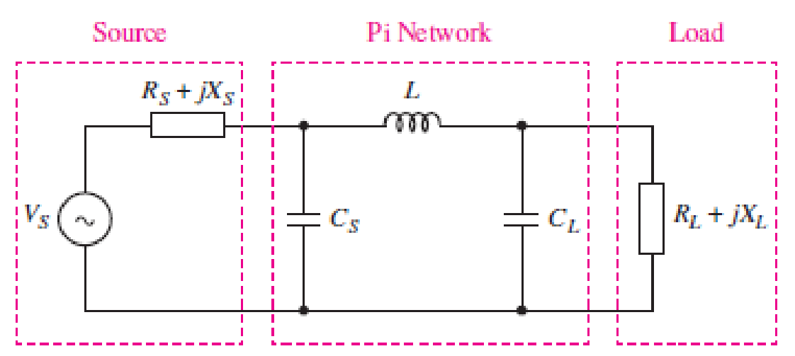
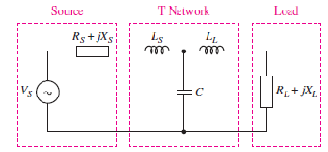
You would like to maximize power transfer to a 50 Ω antenna for VHF communications at 100 MHz. The source has an impedance of 10 + j5 Ω at this frequency. Design a T or Pi matching network for maximum power transfer (see Figs. 11.51 and 11.52). Simulate your design using SPICE, and use an appropriate supporting argument to verify maximum power transfer.
■ FIGURE 11.51
■ FIGURE 11.52
Expert Solution & Answer
Want to see the full answer?
Check out a sample textbook solution
Students have asked these similar questions
The impedance of an electrical circuit is (30 − j50) ohms. Determine (a) the resistance, (b) the capacitance, (c) the modulus of the impedance, and (d) the current flowing and its phase angle, when the circuit is connected to a 240V, 50 Hz supply.
Problem 11.34. At full load, a commercially available 106 hp, three-phase induction motor operates at an efficiency of 96% and a power factor of 0.87 lag. The motor is supplied from a three-phase outlet with a line-voltage rating of 208 V.
1. What is the magnitude of the line current in Ampere drawn from the 208 V outlet? (1 hp = 746 W).
2. Calculate the reactive power in kVAR supplied to the motor.
2) The net inlet to a factory powered by a 2300 volt infinite busis measured as 765 A, for a lag 0.92 power factor. although mostloads is inductive, the input power factor has been improved by installing asynchronous capacitor operating at its nominal value of 1000 KVA. Determine the factor oforiginal factory power.
Chapter 11 Solutions
Loose Leaf for Engineering Circuit Analysis Format: Loose-leaf
Ch. 11.1 - A current source of 12 cos 2000t A, a 200 ....Ch. 11.2 - Given the phasor voltage across an impedance ,...Ch. 11.2 - Prob. 3PCh. 11.2 - Prob. 4PCh. 11.2 - A voltage source vs is connected across a 4...Ch. 11.3 - If the 30 mH inductor of Example 11.7 is replaced...Ch. 11.4 - Calculate the effective value of each of the...Ch. 11.5 - For the circuit of Fig. 11.16, determine the power...Ch. 11.6 - Prob. 10PCh. 11 - Prob. 1E
Ch. 11 - Determine the power absorbed at t = 1.5 ms by each...Ch. 11 - Calculate the power absorbed at t = 0, t = 0+, and...Ch. 11 - Three elements are connected in parallel: a 1 k...Ch. 11 - Let is = 4u(t) A in the circuit of Fig. 11.28. (a)...Ch. 11 - Prob. 6ECh. 11 - Assuming no transients are present, calculate the...Ch. 11 - Prob. 8ECh. 11 - Prob. 9ECh. 11 - Prob. 10ECh. 11 - The phasor current I=915mA (corresponding to a...Ch. 11 - A phasor voltage V=10045V (the sinusoid operates...Ch. 11 - Prob. 13ECh. 11 - Prob. 14ECh. 11 - Find the average power for each element in the...Ch. 11 - (a) Calculate the average power absorbed by each...Ch. 11 - Prob. 17ECh. 11 - Prob. 18ECh. 11 - Prob. 19ECh. 11 - The circuit in Fig. 11.36 has a series resistance...Ch. 11 - Prob. 21ECh. 11 - Prob. 22ECh. 11 - Prob. 23ECh. 11 - Prob. 24ECh. 11 - Prob. 25ECh. 11 - Prob. 26ECh. 11 - Prob. 27ECh. 11 - Prob. 28ECh. 11 - Prob. 29ECh. 11 - Prob. 30ECh. 11 - Prob. 31ECh. 11 - Prob. 32ECh. 11 - Prob. 33ECh. 11 - (a) Calculate both the average and rms values of...Ch. 11 - Prob. 35ECh. 11 - FIGURE 11.43 Calculate the power factor of the...Ch. 11 - Prob. 37ECh. 11 - Prob. 38ECh. 11 - Prob. 40ECh. 11 - Prob. 41ECh. 11 - Prob. 42ECh. 11 - Prob. 43ECh. 11 - Compute the complex power S (in polar form) drawn...Ch. 11 - Calculate the apparent power, power factor, and...Ch. 11 - Prob. 46ECh. 11 - Prob. 48ECh. 11 - Prob. 49ECh. 11 - Prob. 50ECh. 11 - Prob. 51ECh. 11 - Prob. 52ECh. 11 - FIGURE 11.49 Instead of including a capacitor as...Ch. 11 - Prob. 54ECh. 11 - A load is drawing 10 A rms when connected to a...Ch. 11 - For the circuit of Fig. 11.50, assume the source...Ch. 11 - Prob. 57ECh. 11 - A source 45 sin 32t V is connected in series with...Ch. 11 - Prob. 60ECh. 11 - FIGURE 11.51 The circuit in Fig. 11.51 uses a Pi...Ch. 11 - Prob. 62ECh. 11 - Prob. 63ECh. 11 - You would like to maximize power transfer to a 50 ...
Knowledge Booster


Learn more about
Need a deep-dive on the concept behind this application? Look no further. Learn more about this topic, electrical-engineering and related others by exploring similar questions and additional content below.Similar questions
- An electrical load of 250Kva has a pf of 0.65 inductive. Connects to the same network a 75kW star synchronous motor, with 88% efficiency, to raise the pf of the installation at 0.85 inductive.a) Calculate the apparent pf of the synchronous motor and the pf at which it will work.b) If the supply voltage is 380V, and the motor has a synchronous impedanceof j0.5 ohms per phase determine the induced emf of the machine.arrow_forwardA 3-phase, 50 Hz, 3000 V motor develops 600 H.P. (447·6 kW), the power factor being 0·75 lagging and the efficiency 0·93. A bank of capacitors is connected in delta across the supply terminals and power factor raised to 0·9 lagging. Each of the capacitance units is built of five similar 600-V capacitors. Determine the leading Kvar taken by each three sets.arrow_forward2) An industrial plant is supplied from 400V 50Hz power system. The plant consists of(i) 2x50kW pure resistive heating furnace(ii) 5x25kW induction motor having a lagging power factor of 0.85(iii) A compressor unit drawing 80kW active power and 60kVAr inductive reactive power.Calculate per phase capacitance of delta (∆) connected reactive power compensation system to setthe power factor of the industrial power plant to 0.98 leading.arrow_forward
- When connected to a 120 V (rms), 60-Hz power line, a load absorbs 4kW at a lagging power factor of 0.8. Find the value of Capacitance, C, necessary to raise the power factor to 0.95 lagging.arrow_forwardAn industrial plant is supplied from 400V 50Hz power system. The plant consists of (i) 2x50kW pure resistive heating furnace(ii) 5x25kW induction motor having a lagging power factor of 0.85(iii) A compressor unit drawing 80kW active power and 60kVAr inductive reactive power. Calculate per phase capacitance of delta (∆) connected reactive power compensation system to set the power factor of the industrial power plant to 0.98 leading.arrow_forwardDesign a power factor correction circuit with the value of parallel capacitance needed tocorrect a load of 179 kVAR at 0.85 lagging pf to unity pf. Assume that the load issupplied by a 110-V (rms), 60-Hz line.arrow_forward
- Calculate the energy stored in the coupled coils at t = 10 ms if M = 0.2 H and vs = 12 cos 10t V.arrow_forwardf. A residential air conditioning unit with an SEER of 14 serves a single-detached family residence in Quezon City, Philippines having an annual cooling load hours of 6,116 hours. The total cooling load is 36,000 Btu/hr. Calculate the annual operating cost for the A/C unit if the energy cost is Php 7.96/kW-hr.arrow_forwardThe load on a 120-V, 60 Hz supply is 5KW (resistive), 8 KVAR (inductive), and 2 KVAR (capacitive). Find the following: a) total kilovolt-amperes, b)power factor of the combined loads, c) current drawn from the supply, d) capacitance needed to establish unity power factor, e) capacitive reactance needed to establish unity power factor, f) the current drawn from the supply at unity p.f.arrow_forward
- A 5-ohm resistor is connected in series with a 25 micro-farad capacitor. A source voltage of158 volts, 50 Hz supplies the combination. Determine the following: e. Reactive power supplied by the sourcef. Apparent power of the circuitg. Power factor of the entire circuitarrow_forwardA transmission line of impedance (0.05 + j0.02) pu interconnects the buses of a switchyard and a bulk supply point. The receiving end apparent power is (1.0 + j0.6) pu and sending end voltage, 1/0°pu. Estimate the following: i) Receiving end voltage after two iterations ii) Perform two further iterations to test the convergence of the value of receiving end voltage deduced in (i) iii) load currentarrow_forwardAn investor own two large stores at Dubai. Both malls are connected in parallel and operating at an unknown voltage. The local utility system voltage is 13.8 kVrms and supplied power to the malls through a feeder line with impedance equal to 1+j2.5 ohms. Store 1 is consuming 400 kW at 0.8 pf lagging while Store 2 is consuming 300 kVAR at 0.75 pf lagging. Determine the following: a) The stores' operating rms voltages. b) The total real and reactive power of the ehole system. c) The overall pf of the whole system.arrow_forward
arrow_back_ios
SEE MORE QUESTIONS
arrow_forward_ios
Recommended textbooks for you
 Introductory Circuit Analysis (13th Edition)Electrical EngineeringISBN:9780133923605Author:Robert L. BoylestadPublisher:PEARSON
 Delmar's Standard Textbook Of ElectricityElectrical EngineeringISBN:9781337900348Author:Stephen L. HermanPublisher:Cengage Learning
 Programmable Logic ControllersElectrical EngineeringISBN:9780073373843Author:Frank D. PetruzellaPublisher:McGraw-Hill Education
 Fundamentals of Electric CircuitsElectrical EngineeringISBN:9780078028229Author:Charles K Alexander, Matthew SadikuPublisher:McGraw-Hill Education
 Electric Circuits. (11th Edition)Electrical EngineeringISBN:9780134746968Author:James W. Nilsson, Susan RiedelPublisher:PEARSON
 Engineering ElectromagneticsElectrical EngineeringISBN:9780078028151Author:Hayt, William H. (william Hart), Jr, BUCK, John A.Publisher:Mcgraw-hill Education,
Introductory Circuit Analysis (13th Edition)
Electrical Engineering
ISBN:9780133923605
Author:Robert L. Boylestad
Publisher:PEARSON
Delmar's Standard Textbook Of Electricity
Electrical Engineering
ISBN:9781337900348
Author:Stephen L. Herman
Publisher:Cengage Learning
Programmable Logic Controllers
Electrical Engineering
ISBN:9780073373843
Author:Frank D. Petruzella
Publisher:McGraw-Hill Education
Fundamentals of Electric Circuits
Electrical Engineering
ISBN:9780078028229
Author:Charles K Alexander, Matthew Sadiku
Publisher:McGraw-Hill Education
Electric Circuits. (11th Edition)
Electrical Engineering
ISBN:9780134746968
Author:James W. Nilsson, Susan Riedel
Publisher:PEARSON
Engineering Electromagnetics
Electrical Engineering
ISBN:9780078028151
Author:Hayt, William H. (william Hart), Jr, BUCK, John A.
Publisher:Mcgraw-hill Education,
Types of Energy for Kids - Renewable and Non-Renewable Energies; Author: Smile and Learn - English;https://www.youtube.com/watch?v=w16-Uems2Qo;License: Standard Youtube License