
Concept explainers
Videos
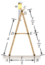
A stepladder of negligible weight is constructed as shown in Figure P12.40, with AC = BC = ℓ. A painter of mass m stands on the ladder a distance d from the bottom. Assuming the floor is frictionless, find (a) the tension in the horizontal bar DE connecting the two halves of the ladder, (b) the normal forces at A and B, and (c) the components of the reaction force at the single hinge C that the left half of the ladder exerts on the right half. Suggestion: Treat the ladder as a single object, but also treat each half of the ladder separately.
Figure P12.40 Problems 40 and 41.

Trending nowThis is a popular solution!

Chapter 12 Solutions
Bundle: Physics for Scientists and Engineers with Modern Physics, Loose-leaf Version, 10th + WebAssign Printed Access Card for Serway/Jewett's Physics for Scientists and Engineers, 10th, Multi-Term


- A stepladder of negligible weight is constructed as shown in Figure P10.73, with AC = BC = ℓ. A painter of mass m stands on the ladder a distance d from the bottom. Assuming the floor is frictionless, find (a) the tension in the horizontal bar DE connecting the two halves of the ladder, (b) the normal forces at A and B, and (c) the components of the reaction force at the single hinge C that the left half of the ladder exerts on the right half. Suggestion: Treat the ladder as a single object, but also treat each half of the ladder separately. Figure P10.73 Problems 73 and 74.arrow_forwardA stepladder of negligible weight is constructed as shown in Figure P10.73, with AC = BC = = 4.00 m. A painter of mass m = 70.0 kg stands on the ladder d = 3.00 m from the bottom. Assuming the floor is frictionless, find (a) the tension in the horizontal bar DE connecting the two halves of the ladder, (b) the normal forces at A and B, and (c) the components of the reaction force at the single hinge C that the left half of the ladder exerts on the right half. Suggestion: Treat the ladder as a single object, but also treat each half of the ladder separately.arrow_forwardRuby, with mass 55.0 kg, is trying to reach a box on a high shelf by standing on her tiptoes. In this position, half her weight is supported by the normal force exerted by the floor on the toes of each foot as shown in Figure P14.75A. This situation can be modeled mechanically by representing the force on Rubys Achilles tendon with FA and the force on her tibia as FT as shown in Figure P14.75B. What is the value of the angle and the magnitudes of the forces FA and FT? FIGURE P14.75arrow_forward
- Why is the following situation impossible? A uniform beam of mass mk = 3.00 kg and length = 1.00 m supports blocks with masses m1 = 5.00 kg and m2 = 15.0 kg at two positions as shown in Figure P12.2. The beam rests on two triangular blocks, with point P a distance d = 0.300 m to the right of the center of gravity of the beam. The position of the object of mass m2 is adjusted along the length of the beam until the normal force on the beam at O is zero. Figure P12.2arrow_forwardA 10.0-kg monkey climbs a uniform ladder with weight 1.20 102 N and length L = 3.00 m as shown in Figure P12.14. The ladder rests against the wall and makes an angle of = 60.0 with the ground. The upper and lower ends of the ladder rest on frictionless surfaces. The lower end is connected to the wall by a horizontal rope that is frayed and can support a maximum tension of only 80.0 N. (a) Draw a force diagram for the ladder. (b) Find the normal force exerted on the bottom of the ladder. (c) Find the tension in the rope when the monkey is two-thirds of the way up the ladder. (d) Find the maximum distance d that the monkey can climb up the ladder before the rope breaks. (e) If the horizontal surface were rough and the rope were removed, how would your analysis of the problem change? What other information would you need to answer parts (c) and (d)? Figure P12.14arrow_forwardA bridge of length 50.0 m and mass 8.00 104 kg is supported on a smooth pier at each end as shown in Figure P12.25. A truck of mass 3.00 104 kg is located 15.0 m from one end. What are the forces on the bridge at the points of support? Figure P12.25arrow_forward
- A uniform beam resting on two pivots has a length L = 6.00 m and mass M = 90.0 kg. The pivot under the left end exerts a normal force n1 on the beam, and the second pivot located a distance = 4.00 m from the left end exerts a normal force n2. A woman of mass m = 55.0 kg steps onto the left end of the beam and begins walking to the right as in Figure P10.28. The goal is to find the womans position when the beam begins to tip. (a) What is the appropriate analysis model for the beam before it begins to tip? (b) Sketch a force diagram for the beam, labeling the gravitational and normal forces acting on the beam and placing the woman a distance x to the right of the first pivot, which is the origin. (c) Where is the woman when the normal force n1 is the greatest? (d) What is n1 when the beam is about to tip? (e) Use Equation 10.27 to find the value of n2 when the beam is about to tip. (f) Using the result of part (d) and Equation 10.28, with torques computed around the second pivot, find the womans position x when the beam is about to tip. (g) Check the answer to part (e) by computing torques around the first pivot point. Figure P10.28arrow_forwardConsider a nanotube with a Youngs modulus of 2.130 1012 N/m2 that experiences a tensile stress of 5.3 1010 N/m2. Steel has a Youngs modulus of about 2.000 1011 Pa. How much stress would cause a piece of steel to experience the same strain as the nanotube?arrow_forwardProblems 33 and 34 are paired. One end of a uniform beam that weighs 2.80 102 N is attached to a wall with a hinge pin. The other end is supported by a cable making the angles shown in Figure P14.33. Find the tension in the cable. FIGURE P14.33 Problems 33 and 34.arrow_forward
- Three forces are exerted on the disk shown in Figure P12.71,and their magnitudes are F3 = 2F2 = 2F1. The disks outer rimhas radius R, and the inner rim has radius R/2. As shown in thefigure, F1 and F3 are tangent to the outer rim of the disk, and F2 is tangent to the inner rim. F3 is parallel to the x axis, F2 is parallel to the y axis, and F1 makes a 45 angle with the negative x axis. Find expressions for the magnitude of each torque exertedaround the center of the disk in terms of R and F1. FIGURE P12.71 Problems 71-75arrow_forwardWhy is the following situation impossible? A worker in a factory pulls a cabinet across the floor using a rope as shown in Figure P12.36a. The rope make an angle = 37.0 with the floor and is tied h1 = 10.0 cm from the bottom of the cabinet. The uniform rectangular cabinet has height = 100 cm and width w = 60.0 cm, and it weighs 400 N. The cabinet slides with constant speed when a force F = 300 N is applied through the rope. The worker tires of walking backward. He fastens the rope to a point on the cabinet h2 = 65.0 cm off the floor and lays the rope over his shoulder so that he can walk forward and pull as shown in Figure P12.36b. In this way, the rope again makes an angle of = 37.0 with the horizontal and again has a tension of 300 N. Using this technique, the worker is able to slide the cabinet over a long distance on the floor without tiring. Figure P12.36 Problems 36 and 44.arrow_forwardA uniform wire (Y = 2.0 1011 N/m2) is subjected to a longitudinal tensile stress of 4.0 107 N/m2. What is the fractional change in the length of the wire?arrow_forward
 Principles of Physics: A Calculus-Based TextPhysicsISBN:9781133104261Author:Raymond A. Serway, John W. JewettPublisher:Cengage Learning
 Physics for Scientists and Engineers with Modern ...PhysicsISBN:9781337553292Author:Raymond A. Serway, John W. JewettPublisher:Cengage Learning
 Physics for Scientists and EngineersPhysicsISBN:9781337553278Author:Raymond A. Serway, John W. JewettPublisher:Cengage Learning
 Physics for Scientists and Engineers: Foundations...PhysicsISBN:9781133939146Author:Katz, Debora M.Publisher:Cengage Learning