
Concept explainers
Videos
SSMA uniform ladder is 10 m long and weighs 200 N. In Fig. 12-78, the ladder leans against a vertical, frictionless wall at height h = 8.0 m above the ground. A horizontal force
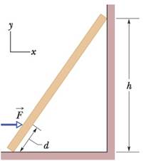
Figure 12-78 Problem 73.

Trending nowThis is a popular solution!

Chapter 12 Solutions
Fundamentals of Physics, Volume 1, Chapter 1-20
Additional Science Textbook Solutions
Essential University Physics: Volume 1 (3rd Edition)
College Physics (10th Edition)
Glencoe Physical Science 2012 Student Edition (Glencoe Science) (McGraw-Hill Education)
College Physics: A Strategic Approach (4th Edition)
University Physics (14th Edition)
Conceptual Physical Science (6th Edition)


- As part of an engineering design, a load of mass M2=10 kg is to be suspended from the far end of a beam of mass M1=8kg. A horizontal cable supporting the beam attaches to the beam at a distance of d=2m from a joint/hinge. The length of the beam is L=7m. The beam makes an angle of 55 degrees with the horizontal. M, 2 a. What magnitude of force should the cable be able to withstand in this setup? b. What magnitude of force should the joint/hinge be able to withstand in this setup?arrow_forwardIn the figure, one end of a uniform beam of weight 100 N is hinged to a wall; the other end is supported by a wire that makes angles 8- 29 with both wall and beam. Find (a) the tension in the wire and the (b) horizontal anid (c) vertical components of the force of the hinge on the beam. Hinge (a) Number Units Units (b) Number Units (c) Nurmiberarrow_forwardA 10 kg ladder has a length of 8 feet and leans on a vertical wall with an angle of 30 degree. Determine the force exerted by the tip of the ladder on the vertical wall and the force exerted by its foot on the horizontal ground. ( complete solution)arrow_forward
- A uniform rod is attached to a wall by a hinge at its base. The rod has a mass of 7.5 kg, a length of 2.3 m, is at an angle of 29° above the horizontal, and is held in place by a horizontal cord attached to the other end of the rod and bolted to the wall above the base of the rod. (a) Determine the tension in the cord. 63.715 X Where is a convenient point about which to take the torques? See if you can write an expression for the torque in terms of the force producing the torque and the perpendicular distance from the line of action of the force to the point about which we have specified to determine the torque. See if you can write a second condition of equilibrium that will allow you to determine the tension in the cord. N (b) Determine the horizontal and vertical components of the force exerted on the rod by the hinge. 36.788 X FH = Now that you know the tension in the cord from part (a), see if you can write a first condition of equilibrium statement that will allow you to…arrow_forwardA metal rod of mass M = 6 kg and length L = 0.5 m, is attached at one end by a hinge to a vertical wall. It is initially supported at the other end so that it is in static equilibrium and lies horizontally. (a) (i) Determine the magnitude and direction of the force on the bar due to the support. (ii) Determine the magnitude and direction of the force on the bar due to the hinge. (b) Show that the moment of inertia of the bar about the end that is attached to the wall is IH = 0.5 kg m2 (c) The support is removed and the bar swings down about the end attached to the hinge. What is the acceleration of a point on the end of the rod just after the support is removed (at this instant the acceleration vector will point directly down)? Give your result in terms of g.arrow_forwardA crate with a mass of M = 64.5 kg is suspended by a rope from the endpoint of a uniform boom. The boom has a mass of m = 119 kg and a length of | = 6.13 m. The midpoint of the boom is supported by another rope which is horizontal and is attached to the wall as shown in the figure. m 1 M The boom makes an angle of 0 = 52.0° with the vertical wall. Calculate the tension in the vertical rope. Submit Answer Incorrect. Tries 2/12 Previous Tries Submit Answer What is the tension in the horizontal rope? Incorrect. Tries 1/12 Previous Triesarrow_forward
- (b) A heavy uniform rod AB of weight W is hinged at A to a fixed point. It is pulled aside by a horizontal force P so that it rests inclined at an angle 0 to the vertical. Show that (i) the magnitude of the force Pis 1-cos2e W 2V 1-sin24 (ii) the reaction at the hinge is V3+ sec*0arrow_forwardA 73 kg man stands on a level bridge of length L. He is at distance L/4 from one end. The bridge is uniform and weighs 2.7 kN.What are the magnitudes of the vertical forces on the bridge from its supports at (a) the end farther from him and (b) the nearer end?arrow_forward- 5. Two identical, uniform beams of length 3 m and weighing 260 N each are connected at one end by a frictionless hinge. A light horizontal crossbar, attached at the midpoints of the beams maintains an angle 50° between the beams. The beams are suspended from the ceiling by vertical wires so they form a V. See figure. (a) What force does the crossbar exert on each beam? (b) Is the crossbar under compression or tension, i.e. are the ends of the crossbar being pushed together or stretched farther apart? (c) What force (magnitude and direction) does the hinge exert on each beam? Crossbar Hingearrow_forward
- 11-30 Two blocks are suspended on a continuous inex- tensible cord as shown in Fig. P11-30. Determine the angle O for equilibrium if the masses of blocks A and B are 50 and 40 kg, respectively. Fig. P11-30arrow_forwardsuppose the length L of the uniform bar is 3.4 m and its weight is 180 N. Also, let the block's weight W = 310 N and the angle 0 = 41°. The wire can withstand a maximum tension of 440 N. (a) What is the maximum possible distance x before the wire breaks? With the block placed at this maximum x, what are the (b) horizontal and (c) vertical components of the force on the bar from the hinge at A?arrow_forwardThe column is built up by gluing the two identical boards together. If the wood has an allowable normal stress of σallowσallowx = 5.6 MPaMPa , determine the maximum allowable eccentric force PP that can be applied to the column.arrow_forward
 Physics for Scientists and Engineers: Foundations...PhysicsISBN:9781133939146Author:Katz, Debora M.Publisher:Cengage Learning