
Mechanics of Materials
11th Edition
ISBN: 9780137605514
Author: Russell C. Hibbeler
Publisher: Pearson Education (US)
expand_more
expand_more
format_list_bulleted
Concept explainers
Videos
Textbook Question
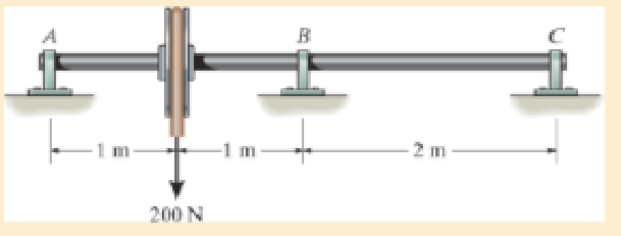
Chapter 12, Problem 7RP
Determine the reactions, then draw the shear and moment diagrams. Use the moment-area theorems. El is constant.
Expert Solution & Answer
Want to see the full answer?
Check out a sample textbook solution
Students have asked these similar questions
Use n=14. Determine the external reactions at the roller and pin supporting the above beam.
Determine the internal reactions (shear and bending moment) at points B, D and F using the method of sections.
Determine the shear and moment equations for the beam section under the triangular load, and the shear and moment equations for the beam section under the rectangular load.
Draw the shear and bending moment diagrams using the area method showing the differential relations that exist between the load, shear and moment at each section of the beam. Label the diagrams properly indicating where the shear and moment values are positive and negative. Also show on the diagram all the maximum and minimum shear and moment values.
Determine the reaction and moment at point D, show the direction of the moment and Reaction, draw the Shear force and Bending moment diagrams
From the figure shown, determine the reaction at the support? Also, determine the shear and bending moment at point B?
Chapter 12 Solutions
Mechanics of Materials
Ch. 12.2 - Determine the slope and deflection of end A of the...Ch. 12.2 - Determine the slope and deflection of end A of the...Ch. 12.2 - Determine the slope of end A of the cantilevered...Ch. 12.2 - Determine the maximum deflection of the simply...Ch. 12.2 - Determine the maximum deflection of the simply...Ch. 12.2 - Determine the slope of the simply supported beam...Ch. 12.2 - An L2 steel strap having a thickness of 0.125 in....Ch. 12.2 - The L2 steel blade of the band saw wraps around...Ch. 12.2 - A picture is taken of a man performing a pole...Ch. 12.2 - A torque wrench is used to tighten the nut on a...
Ch. 12.2 - The pipe can be assumed roller supported at its...Ch. 12.2 - Determine the equations of the elastic curve for...Ch. 12.2 - Determine the equations of the elastic curve using...Ch. 12.2 - Determine the maximum deflection of the solid...Ch. 12.2 - Determine the equation of the elastic curve using...Ch. 12.2 - Determine the equations of the elastic curve using...Ch. 12.3 - The shaft supports the two pulley loads shown....Ch. 12.3 - Determine the equation of the elastic curve, the...Ch. 12.3 - Determine the equation of the elastic curve and...Ch. 12.3 - Determine the maximum deflection of the...Ch. 12.3 - Prob. 45PCh. 12.3 - Prob. 46PCh. 12.3 - Prob. 47PCh. 12.3 - Prob. 48PCh. 12.4 - Determine the slope and deflection of end A of the...Ch. 12.4 - Determine the slope and deflection of end A of the...Ch. 12.4 - Determine the slope and deflection of end A of the...Ch. 12.4 - Determine the slope and deflection at A of the...Ch. 12.4 - Prob. 11FPCh. 12.4 - Determine the maximum deflection of the simply...Ch. 12.4 - Determine the slope and deflection at C. El is...Ch. 12.4 - Prob. 54PCh. 12.4 - The composite simply supported steel shaft is...Ch. 12.4 - Determine the maximum deflection of the...Ch. 12.4 - Prob. 60PCh. 12.4 - Determine the slope at A and the maximum...Ch. 12.4 - Determine the displacement of the 20-mm-diameter...Ch. 12.4 - The two force components act on the tire of the...Ch. 12.4 - Determine the slope at B and deflection at C. El...Ch. 12.4 - Prob. 79PCh. 12.5 - The W10 15 cantilevered beam is made of A-36...Ch. 12.5 - The W14 43 simply supported beam is made of A992...Ch. 12.5 - The W14 43 simply supported beam is made of A992...Ch. 12.5 - The W14 43 simply supported beam is made of A-36...Ch. 12.7 - Determine the reactions at the supports A and B,...Ch. 12.7 - Determine the reactions at the supports A, B, and...Ch. 12.7 - Determine the reactions at the supports A and B,...Ch. 12.7 - The beam has a constant E1I1 and is supported by...Ch. 12.8 - Determine the reaction at the supports, then draw...Ch. 12.9 - Determine the reactions at the fixed support A and...Ch. 12.9 - Determine the reactions at the fixed support A and...Ch. 12.9 - Determine the reactions at the fixed support A and...Ch. 12.9 - Determine the reaction at the roller B. EI is...Ch. 12.9 - Determine the reaction at the roller B. EI is...Ch. 12.9 - Determine the reaction at the roller support B if...Ch. 12.9 - Determine the reactions at the journal bearing...Ch. 12.9 - Determine the reactions at the supports, then draw...Ch. 12.9 - Determine the reactions at the supports, then draw...Ch. 12.9 - The rim on the flywheel has a thickness t, width...Ch. 12.9 - Determine the moment developed in each corner....Ch. 12 - Determine the equation of the elastic curve. Use...Ch. 12 - Draw the bending-moment diagram for the shaft and...Ch. 12 - Determine the moment reactions at the supports A...Ch. 12 - Specify the slope at A and the maximum deflection....Ch. 12 - Determine the maximum deflection between the...Ch. 12 - Determine the slope at B and the deflection at C....Ch. 12 - Determine the reactions, then draw the shear and...Ch. 12 - El is constant.Ch. 12 - Using the method of superposition, determine the...
Additional Engineering Textbook Solutions
Find more solutions based on key concepts
The triple jump is a track-and-field event in which an athlete gets a running start and tries to leap as far as...
Vector Mechanics For Engineers
Determine the velocity of block D if end A of the rope is pulled down with a speed of vA = 3 m/s.
Engineering Mechanics: Dynamics (14th Edition)
19.8 Calculate the allowable tensile load for the connection shown. The plates are ASTM A36 steel and the weld ...
Applied Statics and Strength of Materials (6th Edition)
Compute the hydraulic radius for a circular drain pipe running half full if its inside diameter is 300 mm.
Applied Fluid Mechanics (7th Edition)
What is the weight in newtons of an object that has a mass of (a) 8 kg, (b) 0.04 kg, (c) 760 Mg?
Statics and Mechanics of Materials (5th Edition)
3.3 It is known that a vertical force of 200 lb is required to remove the nail at C from the board. As the nail...
Vector Mechanics for Engineers: Statics, 11th Edition
Knowledge Booster


Learn more about
Need a deep-dive on the concept behind this application? Look no further. Learn more about this topic, mechanical-engineering and related others by exploring similar questions and additional content below.Similar questions
- Calculate the reaction moment at point Oarrow_forwardFind the equation for the shear force as function of x, V(x), along the x domains A-B (O ≤ x < 5 m) and B-C (5 m s x ≤ 10 m), and draw the shear diagram for the beam. For each step, draw the associated free body diagram and indicate the equations of equilibrium usedarrow_forwardFind the horizontal reaction and vertical reaction at A and also the vertical reaction at B. Determine the Internal forces at point C. Construct the shear and moment equations/functions at segment DE (1.5 < x < 3.0).Note point D is at 1.5m from A and point E is 3.0m from A.arrow_forward
- Q4:Draw the shear force and bending moment diagram for beam shown below. A 3 15 KN 3 m 6 m 9 m Barrow_forward4. Find the reactions at B and D. Weight of the beam is 300 N/m. TIM 400 N/m <-2m-1m Pe=400 N 200 N/m 4 m D 2marrow_forwardA reinforced concrete pier is used to support the stringers for a bridge deck. Draw the shear and moment diagrams for the pier. Assume the columns at A and B exert only vertical reactions on the pier.arrow_forward
- 8 kN/m 9m 6 m B C 4 kN/m Show Transcribed Text Determine the reactions at the supports using the force method. Moreover, draw the moment diagram. El is constant.arrow_forwardThe shear-force diagram for a beam is shown in the figure. Assuming that no couples act as loads on the beam, determine the forces acting on the beam and draw the bending-moment diagram.arrow_forwardThe shear-force diagram for a simple beam is shown in the figure. Determine the loading on the beam and draw the bending-moment diagram, assuming that no couples act as loads on the beam.arrow_forward
- Draw the load and moment diagram that corresponds to the given shear diagram. Assume no couples are applied to the beam. SHOW THE COMPLETE SOLUTION AND STEP-BY-STEP SOLUTION. THANK YOU.arrow_forwardFor the beam shown, find the reactions at the supports and plot the shear-force and bending-moment diagrams. V = 7 kN, V2 = 7 kN, V3 = 100 mm, and V4 = 1300 mm. ATAT V3 (mm) O Provide values at all key points shown in the given shear-force and bending-moment diagrams. (mm) A с B Reaction force R₁ (left) = E D 0.00 F +V 0.00 X (mm) 7 kN and reaction force R₂ (right) = P 7 kN. Q 0.00arrow_forwardde The beam shown supports a load that varies uniformly from 250 N/m at the left end to 0 N/m at the right end. The lengths of the beam segments are d₁=2 m, d₂ = 2 m, and d₂ = 8 m. Reactions Determine the reactions at pin A and roller C. Let positive values indicate upward forces. A= C= Internal Load Determine the internal shear and bending moment at a section passing through point D. Use the standard convention for the meaning of positive shears and bending moments. VD= Mp=arrow_forward
arrow_back_ios
SEE MORE QUESTIONS
arrow_forward_ios
Recommended textbooks for you
 Mechanics of Materials (MindTap Course List)Mechanical EngineeringISBN:9781337093347Author:Barry J. Goodno, James M. GerePublisher:Cengage Learning
Mechanics of Materials (MindTap Course List)
Mechanical Engineering
ISBN:9781337093347
Author:Barry J. Goodno, James M. Gere
Publisher:Cengage Learning
Understanding Shear Force and Bending Moment Diagrams; Author: The Efficient Engineer;https://www.youtube.com/watch?v=C-FEVzI8oe8;License: Standard YouTube License, CC-BY
Bending Stress; Author: moodlemech;https://www.youtube.com/watch?v=9QIqewkE6xM;License: Standard Youtube License