
Mechanics of Materials
11th Edition
ISBN: 9780137605514
Author: Russell C. Hibbeler
Publisher: Pearson Education (US)
expand_more
expand_more
format_list_bulleted
Concept explainers
Videos
Textbook Question
Chapter 12.4, Problem 71P
Determine the displacement of the 20-mm-diameter A-36 steel shaft at D.
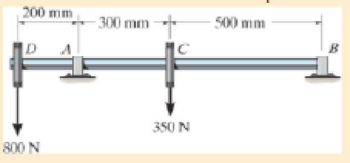
Prob. 12–71
Expert Solution & Answer
Want to see the full answer?
Check out a sample textbook solution
Students have asked these similar questions
If a solid shaft has a diameter of 4 inches. Determine the polar section modulus
Determine the absolute maximum bending stress in the 1.5-in.-diameter shaft. The shaft is supported by a thrust bearing at A and a journal bearing at B.
If the shaft is made from A-36 steel having allowable shear stress of tallow = 75 MPa, determine the minimum dimension a for the cross-section to the nearest millimeter. Also, find the corresponding angle of twist at end B.
Chapter 12 Solutions
Mechanics of Materials
Ch. 12.2 - Determine the slope and deflection of end A of the...Ch. 12.2 - Determine the slope and deflection of end A of the...Ch. 12.2 - Determine the slope of end A of the cantilevered...Ch. 12.2 - Determine the maximum deflection of the simply...Ch. 12.2 - Determine the maximum deflection of the simply...Ch. 12.2 - Determine the slope of the simply supported beam...Ch. 12.2 - An L2 steel strap having a thickness of 0.125 in....Ch. 12.2 - The L2 steel blade of the band saw wraps around...Ch. 12.2 - A picture is taken of a man performing a pole...Ch. 12.2 - A torque wrench is used to tighten the nut on a...
Ch. 12.2 - The pipe can be assumed roller supported at its...Ch. 12.2 - Determine the equations of the elastic curve for...Ch. 12.2 - Determine the equations of the elastic curve using...Ch. 12.2 - Determine the maximum deflection of the solid...Ch. 12.2 - Determine the equation of the elastic curve using...Ch. 12.2 - Determine the equations of the elastic curve using...Ch. 12.3 - The shaft supports the two pulley loads shown....Ch. 12.3 - Determine the equation of the elastic curve, the...Ch. 12.3 - Determine the equation of the elastic curve and...Ch. 12.3 - Determine the maximum deflection of the...Ch. 12.3 - Prob. 45PCh. 12.3 - Prob. 46PCh. 12.3 - Prob. 47PCh. 12.3 - Prob. 48PCh. 12.4 - Determine the slope and deflection of end A of the...Ch. 12.4 - Determine the slope and deflection of end A of the...Ch. 12.4 - Determine the slope and deflection of end A of the...Ch. 12.4 - Determine the slope and deflection at A of the...Ch. 12.4 - Prob. 11FPCh. 12.4 - Determine the maximum deflection of the simply...Ch. 12.4 - Determine the slope and deflection at C. El is...Ch. 12.4 - Prob. 54PCh. 12.4 - The composite simply supported steel shaft is...Ch. 12.4 - Determine the maximum deflection of the...Ch. 12.4 - Prob. 60PCh. 12.4 - Determine the slope at A and the maximum...Ch. 12.4 - Determine the displacement of the 20-mm-diameter...Ch. 12.4 - The two force components act on the tire of the...Ch. 12.4 - Determine the slope at B and deflection at C. El...Ch. 12.4 - Prob. 79PCh. 12.5 - The W10 15 cantilevered beam is made of A-36...Ch. 12.5 - The W14 43 simply supported beam is made of A992...Ch. 12.5 - The W14 43 simply supported beam is made of A992...Ch. 12.5 - The W14 43 simply supported beam is made of A-36...Ch. 12.7 - Determine the reactions at the supports A and B,...Ch. 12.7 - Determine the reactions at the supports A, B, and...Ch. 12.7 - Determine the reactions at the supports A and B,...Ch. 12.7 - The beam has a constant E1I1 and is supported by...Ch. 12.8 - Determine the reaction at the supports, then draw...Ch. 12.9 - Determine the reactions at the fixed support A and...Ch. 12.9 - Determine the reactions at the fixed support A and...Ch. 12.9 - Determine the reactions at the fixed support A and...Ch. 12.9 - Determine the reaction at the roller B. EI is...Ch. 12.9 - Determine the reaction at the roller B. EI is...Ch. 12.9 - Determine the reaction at the roller support B if...Ch. 12.9 - Determine the reactions at the journal bearing...Ch. 12.9 - Determine the reactions at the supports, then draw...Ch. 12.9 - Determine the reactions at the supports, then draw...Ch. 12.9 - The rim on the flywheel has a thickness t, width...Ch. 12.9 - Determine the moment developed in each corner....Ch. 12 - Determine the equation of the elastic curve. Use...Ch. 12 - Draw the bending-moment diagram for the shaft and...Ch. 12 - Determine the moment reactions at the supports A...Ch. 12 - Specify the slope at A and the maximum deflection....Ch. 12 - Determine the maximum deflection between the...Ch. 12 - Determine the slope at B and the deflection at C....Ch. 12 - Determine the reactions, then draw the shear and...Ch. 12 - El is constant.Ch. 12 - Using the method of superposition, determine the...
Knowledge Booster


Learn more about
Need a deep-dive on the concept behind this application? Look no further. Learn more about this topic, mechanical-engineering and related others by exploring similar questions and additional content below.Similar questions
- Determine the absolute maximum shear stress in the shaft of Problemarrow_forwardDetermine the slope of the 50-mm-diameter A-36 steel shaft at the journal bearings at A and B. The bearings exert only vertical reactions on the shaft.arrow_forwardDetermine the smallest allowable diameter of the shaft. The shaft is supported by a thrust bearing at A and a journal bearing at B. The allowable bending stress is sallow = 22 ksi.arrow_forward
- The shaft is subjected to the vertical and horizontal loadings of two pulleys D and E as shown. It is supported on two journal bearings at A and B which offer no resistance to axial loading. Furthermore, the coupling to the motor at C can be assumed not to offer any support to the shaft. Determine the required diameter d of the shaft if the allowable bending stress is sallow = 180 MPa.arrow_forward10-46. The A992 steel shaft has a diameter of 50 mm and is subjected to the distributed loadings shown. Determine the ahsolute maximum shear stress in the shaft and plot a graph of the angle of twist of the shaft in radians versus I. SO0 N- 1000 N-m/m *o.s "asmarrow_forwardDetermine the absolute maximum bending stress in the 2-in.-diameter shaft. There is a journal bearing at A and a thrust bearing at B.arrow_forward
- The 50-mm-diameter shaft is supported by journal bearings at A and B. If the pulleys Cand D are subjected to the loadings shown, determine the absolute maximum bendingstress in the shaft.arrow_forwardThe 60-mm-diameter solid shaft is made of 2014-T6 aluminum and is subjected to the distributed and concentrated torsional loadings shown. Determine the angle of twist at the free end A of the shaft.arrow_forwardDetermine the slope at A of the 2014-T6 aluminum shaft having a diameter of 100 mm.arrow_forward
- The shaft is supported by a thrust bearing at A and journal bearing at C. If the material has an allowable bending stress of sallow = 24 ksi, determine the required minimum diameter d of the shaft to the nearest 1 16 in.arrow_forward*11-84. Determine, to the nearest millimeter, the smallest allowable diameter of the shaft which is subjected to the concentrated forces. There is a journal bearing at A and a thrust bearing at B. The allowable bending stress is stm = 150 MPa. 0.5m- -0.4 m- a6 m 12 kN 20 kNarrow_forward10-11. The 60-mm-diameter solid shaft is subjected to the distributed and concentrated torsional ladings shown. Determine the absolute maximum and minimum shear stresses in the shaft's surface and specify their locations, measured from the free end. 400 N-m 4 kN-m/m azm S00 N-marrow_forward
arrow_back_ios
SEE MORE QUESTIONS
arrow_forward_ios
Recommended textbooks for you
 International Edition---engineering Mechanics: St...Mechanical EngineeringISBN:9781305501607Author:Andrew Pytel And Jaan KiusalaasPublisher:CENGAGE L
International Edition---engineering Mechanics: St...
Mechanical Engineering
ISBN:9781305501607
Author:Andrew Pytel And Jaan Kiusalaas
Publisher:CENGAGE L
Solids: Lesson 53 - Slope and Deflection of Beams Intro; Author: Jeff Hanson;https://www.youtube.com/watch?v=I7lTq68JRmY;License: Standard YouTube License, CC-BY