
Mechanics of Materials
11th Edition
ISBN: 9780137605514
Author: Russell C. Hibbeler
Publisher: Pearson Education (US)
expand_more
expand_more
format_list_bulleted
Concept explainers
Videos
Textbook Question
Chapter 12.2, Problem 1FP
Determine the slope and deflection of end A of the cantilevered beam. E = 200 GPa and I = 65.0(106) mm4.
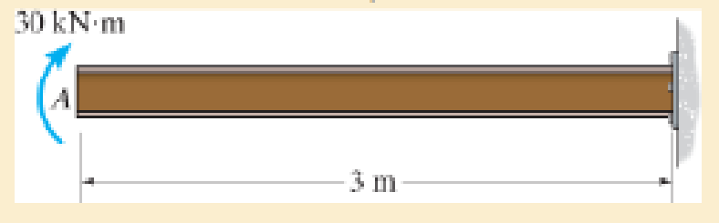
F12–1
Expert Solution & Answer

Learn your wayIncludes step-by-step video

schedule09:07
Students have asked these similar questions
Determine the deflection at point B given the cross-section of the beam and assuming E = 200 GPa.
200 mm
A 20 mm
8 kN
4kN/m
A
200 mm
C
30 mm
1 m
1 m
2 m
2 m
20 mm
3. Set up necessary equations to solve for the beam
reactions. Due to poor construction, roller support B settles
by 12 mm. If E=200 GPa and I=80(10)6 mm4
24KN/m
C
4m
4m
A
Determine the slope and deflection of end A of the cantilevered beam. E = 200 GPa and I = 65.0(106) mm4.
Chapter 12 Solutions
Mechanics of Materials
Ch. 12.2 - Determine the slope and deflection of end A of the...Ch. 12.2 - Determine the slope and deflection of end A of the...Ch. 12.2 - Determine the slope of end A of the cantilevered...Ch. 12.2 - Determine the maximum deflection of the simply...Ch. 12.2 - Determine the maximum deflection of the simply...Ch. 12.2 - Determine the slope of the simply supported beam...Ch. 12.2 - An L2 steel strap having a thickness of 0.125 in....Ch. 12.2 - The L2 steel blade of the band saw wraps around...Ch. 12.2 - A picture is taken of a man performing a pole...Ch. 12.2 - A torque wrench is used to tighten the nut on a...
Ch. 12.2 - The pipe can be assumed roller supported at its...Ch. 12.2 - Determine the equations of the elastic curve for...Ch. 12.2 - Determine the equations of the elastic curve using...Ch. 12.2 - Determine the maximum deflection of the solid...Ch. 12.2 - Determine the equation of the elastic curve using...Ch. 12.2 - Determine the equations of the elastic curve using...Ch. 12.3 - The shaft supports the two pulley loads shown....Ch. 12.3 - Determine the equation of the elastic curve, the...Ch. 12.3 - Determine the equation of the elastic curve and...Ch. 12.3 - Determine the maximum deflection of the...Ch. 12.3 - Prob. 45PCh. 12.3 - Prob. 46PCh. 12.3 - Prob. 47PCh. 12.3 - Prob. 48PCh. 12.4 - Determine the slope and deflection of end A of the...Ch. 12.4 - Determine the slope and deflection of end A of the...Ch. 12.4 - Determine the slope and deflection of end A of the...Ch. 12.4 - Determine the slope and deflection at A of the...Ch. 12.4 - Prob. 11FPCh. 12.4 - Determine the maximum deflection of the simply...Ch. 12.4 - Determine the slope and deflection at C. El is...Ch. 12.4 - Prob. 54PCh. 12.4 - The composite simply supported steel shaft is...Ch. 12.4 - Determine the maximum deflection of the...Ch. 12.4 - Prob. 60PCh. 12.4 - Determine the slope at A and the maximum...Ch. 12.4 - Determine the displacement of the 20-mm-diameter...Ch. 12.4 - The two force components act on the tire of the...Ch. 12.4 - Determine the slope at B and deflection at C. El...Ch. 12.4 - Prob. 79PCh. 12.5 - The W10 15 cantilevered beam is made of A-36...Ch. 12.5 - The W14 43 simply supported beam is made of A992...Ch. 12.5 - The W14 43 simply supported beam is made of A992...Ch. 12.5 - The W14 43 simply supported beam is made of A-36...Ch. 12.7 - Determine the reactions at the supports A and B,...Ch. 12.7 - Determine the reactions at the supports A, B, and...Ch. 12.7 - Determine the reactions at the supports A and B,...Ch. 12.7 - The beam has a constant E1I1 and is supported by...Ch. 12.8 - Determine the reaction at the supports, then draw...Ch. 12.9 - Determine the reactions at the fixed support A and...Ch. 12.9 - Determine the reactions at the fixed support A and...Ch. 12.9 - Determine the reactions at the fixed support A and...Ch. 12.9 - Determine the reaction at the roller B. EI is...Ch. 12.9 - Determine the reaction at the roller B. EI is...Ch. 12.9 - Determine the reaction at the roller support B if...Ch. 12.9 - Determine the reactions at the journal bearing...Ch. 12.9 - Determine the reactions at the supports, then draw...Ch. 12.9 - Determine the reactions at the supports, then draw...Ch. 12.9 - The rim on the flywheel has a thickness t, width...Ch. 12.9 - Determine the moment developed in each corner....Ch. 12 - Determine the equation of the elastic curve. Use...Ch. 12 - Draw the bending-moment diagram for the shaft and...Ch. 12 - Determine the moment reactions at the supports A...Ch. 12 - Specify the slope at A and the maximum deflection....Ch. 12 - Determine the maximum deflection between the...Ch. 12 - Determine the slope at B and the deflection at C....Ch. 12 - Determine the reactions, then draw the shear and...Ch. 12 - El is constant.Ch. 12 - Using the method of superposition, determine the...
Additional Engineering Textbook Solutions
Find more solutions based on key concepts
Professor Crocker is building a cabin on a hillside and has proposed the water system shown in Fig. 7.38 The di...
Applied Fluid Mechanics (7th Edition)
3.37 Determine the magnitude and location of the resultant for the load system shown.
Applied Statics and Strength of Materials (6th Edition)
ICA 17-24
The decay of a radioactive isotope can be theoretically modeled with the following equation, where C0...
Thinking Like an Engineer: An Active Learning Approach (3rd Edition)
Determine the horizontal and vertical components of force at pin B and the normal force the pin at C exerts on ...
Engineering Mechanics: Statics
The car travels up the hill with a speed of v = (0.28) m/s, where s is in meters, measured from A. Determine th...
Engineering Mechanics: Dynamics (14th Edition)
Comprehension Check 7-1
Express the following values using an appropriate Sl prefix such that there are only on...
Thinking Like an Engineer: An Active Learning Approach (4th Edition)
Knowledge Booster


Learn more about
Need a deep-dive on the concept behind this application? Look no further. Learn more about this topic, mechanical-engineering and related others by exploring similar questions and additional content below.Similar questions
- Determine the slope at B and the maximum displacement of the beam. E = 200 GPa, I = 550(106)mmª. Solve Prob. A F using the conjugate-beam method. 2 m 30 kN B 1 m iCarrow_forwardFor the beam loaded as shown, determine the deflection 6 ft from the wall. Use E = 1.5 x 10⁶ psi and I = 40 in.* 80 lb/ft B 8 ftarrow_forward5 kN/m |40 mm For the beam and loading shown, determine the deflection at point B. Use E = 200 GPa. 80 mm B ( 4 kN. 0,6 m- 0.9 marrow_forward
- Determine the slope and deflection of end A of the cantilevered beam. E =250 GPa and I = 70.0 (106) mm. 8 kN A 4 marrow_forwardDetermine the slope and deflection of end A of the cantilevered beam. E = 200 GPa and I = 65.0(106) mª. Moment area method 6 kN 8 3 m B A 20 kN-marrow_forwardDetermine the value of the slope and deflection of the beam at points B and C. E and I are constant over the beam length. (Set a = 4m, w = 5kN/m, E = 200 GPa, I = 114 x 106 mm4)arrow_forward
- Determine the slope and deflection at point B of the beam shown below by the moment- area method. 90 kN A B. 5 m El = constant E = 200 GPa I = 800 (106) mm4arrow_forward2- Determine the slope and deflection at x = 3 m. (EI constant). 2 m 10 kNm 2 m 2 kN/m 2 m 2 m 5 KN 2 marrow_forwardFor the beam and loading shown, determine (a) the slope at point B, (b) the deflection at point D. Use E-200 Gpa , I= 462 (10)-6 A 40 kN/m -4.8 m- B 1.8 m 160 kN Darrow_forward
- The wooden beam is subjected to the load shown. Determine the deflection and the slope at end B. 6 kN 2 kN/m 4 kN B 400 mm 200 mm 3 m -1.5 m–|–1.5 marrow_forwardDetermine the slope at Point A of the beam shown below, measured counterclockwise from the positive x axis. P = 18 kN Wo = 29 kN/m E = 200 GPa I-90.511x10⁶ m² Ensure that iyour answer is in radians. 2P -B -1.8 m- -1.8 m- -1.8 m-arrow_forwardDetermine the slope at points B and C of the beam shown. Take E = 29(103) ksi and I = 600 in4.arrow_forward
arrow_back_ios
SEE MORE QUESTIONS
arrow_forward_ios
Recommended textbooks for you
 Elements Of ElectromagneticsMechanical EngineeringISBN:9780190698614Author:Sadiku, Matthew N. O.Publisher:Oxford University Press
 Mechanics of Materials (10th Edition)Mechanical EngineeringISBN:9780134319650Author:Russell C. HibbelerPublisher:PEARSON
 Thermodynamics: An Engineering ApproachMechanical EngineeringISBN:9781259822674Author:Yunus A. Cengel Dr., Michael A. BolesPublisher:McGraw-Hill Education
 Control Systems EngineeringMechanical EngineeringISBN:9781118170519Author:Norman S. NisePublisher:WILEY
 Mechanics of Materials (MindTap Course List)Mechanical EngineeringISBN:9781337093347Author:Barry J. Goodno, James M. GerePublisher:Cengage Learning
 Engineering Mechanics: StaticsMechanical EngineeringISBN:9781118807330Author:James L. Meriam, L. G. Kraige, J. N. BoltonPublisher:WILEY
Elements Of Electromagnetics
Mechanical Engineering
ISBN:9780190698614
Author:Sadiku, Matthew N. O.
Publisher:Oxford University Press
Mechanics of Materials (10th Edition)
Mechanical Engineering
ISBN:9780134319650
Author:Russell C. Hibbeler
Publisher:PEARSON
Thermodynamics: An Engineering Approach
Mechanical Engineering
ISBN:9781259822674
Author:Yunus A. Cengel Dr., Michael A. Boles
Publisher:McGraw-Hill Education
Control Systems Engineering
Mechanical Engineering
ISBN:9781118170519
Author:Norman S. Nise
Publisher:WILEY
Mechanics of Materials (MindTap Course List)
Mechanical Engineering
ISBN:9781337093347
Author:Barry J. Goodno, James M. Gere
Publisher:Cengage Learning
Engineering Mechanics: Statics
Mechanical Engineering
ISBN:9781118807330
Author:James L. Meriam, L. G. Kraige, J. N. Bolton
Publisher:WILEY
Solids: Lesson 53 - Slope and Deflection of Beams Intro; Author: Jeff Hanson;https://www.youtube.com/watch?v=I7lTq68JRmY;License: Standard YouTube License, CC-BY