
MECHANICS OF MATERIALS (LOOSE)-W/ACCESS
10th Edition
ISBN: 9780134583228
Author: HIBBELER
Publisher: PEARSON
expand_more
expand_more
format_list_bulleted
Concept explainers
Videos
Textbook Question
Chapter 12.2, Problem 12.2P
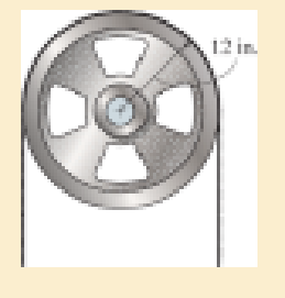
The L2 steel blade of the band saw wraps around the pulley having a radius of 12 in. Determine the maximum normal stress in the blade. The blade has a width of 0.75 in. and a thickness of 0.0625 in.
Prob. 12–2
Expert Solution & Answer
Want to see the full answer?
Check out a sample textbook solution
Students have asked these similar questions
The bolt has a diameter of 20 (mm) and passes through a tube that has an inner diameter of 50 (mm) and an outer diameter of 60 (mm). If the bolt and tube are made of A-36 steel, determine the normal stress in the tube and bolt when a force of 40 (kN) is applied to the bolt. Assume the end caps are rigid.
The shaft is hollow from A to B and solid from B to C. Determine the maximum shear stress in the shaft. The shaft has an outer diameter of 80 mm, and the thickness of the wall of the hollow segment is 10 mm.
The cylindrical pressure vessel has an inner radius of 1.25 m and a wall thickness of 15 mm. It is made from steel plates that are welded along the 45° seam. Determine the normal and shear stress components along this seam if the vessel is subjected to an internal pressure of 8 MPa.
Chapter 12 Solutions
MECHANICS OF MATERIALS (LOOSE)-W/ACCESS
Ch. 12.2 - In each case, determine the internal bending...Ch. 12.2 - Determine the slope and deflection of end A of the...Ch. 12.2 - Determine the slope and deflection of end A of the...Ch. 12.2 - Determine the slope of end A of the cantilevered...Ch. 12.2 - Determine the maximum deflection of the simply...Ch. 12.2 - Determine the maximum deflection of the simply...Ch. 12.2 - Determine the slope of the simply supported beam...Ch. 12.2 - An L2 steel strap having a thickness of 0.125 in....Ch. 12.2 - The L2 steel blade of the band saw wraps around...Ch. 12.2 - A picture is taken of a man performing a pole...
Ch. 12.2 - El is constant. Prob. 124Ch. 12.2 - Determine the deflection of end C of the...Ch. 12.2 - Determine the elastic curve for the cantilevered...Ch. 12.2 - The A-36 steel beam has a depth of 10 in. and is...Ch. 12.2 - Determine the equations of the elastic curve using...Ch. 12.2 - Determine the equations of the elastic curve for...Ch. 12.2 - Determine the equations of the elastic curve using...Ch. 12.2 - Determine the equations of the elastic curve using...Ch. 12.2 - Draw the bending-moment diagram for the shaft and...Ch. 12.2 - Determine the maximum deflection of the beam and...Ch. 12.2 - The simply supported shaft has a moment of inertia...Ch. 12.2 - A torque wrench is used to tighten the nut on a...Ch. 12.2 - The pipe can be assumed roller supported at its...Ch. 12.2 - Determine the equations of the elastic curve for...Ch. 12.2 - The bar is supported by a roller constraint at B,...Ch. 12.2 - Determine the deflection at B of the bar in Prob....Ch. 12.2 - Determine the equations of the elastic curve using...Ch. 12.2 - Determine the maximum deflection of the solid...Ch. 12.2 - Determine the elastic curve for the cantilevered...Ch. 12.2 - Determine the equations of the elastic curve using...Ch. 12.2 - Determine the equations of the elastic curve using...Ch. 12.2 - The floor beam of the airplane is subjected to the...Ch. 12.2 - Determine the maximum deflection of the simply...Ch. 12.2 - The beam is made of a material having a specific...Ch. 12.2 - Determine the slope at end B and the maximum...Ch. 12.2 - Determine the equation of the elastic curve using...Ch. 12.2 - Determine the equations of the elastic curve using...Ch. 12.3 - The shaft is supported at A by a journal bearing...Ch. 12.3 - The shaft supports the two pulley loads shown....Ch. 12.3 - The beam is made of a ceramic material. If it is...Ch. 12.3 - Determine the equation of the elastic curve, the...Ch. 12.3 - The beam is subjected to the load shown. Determine...Ch. 12.3 - Determine the equation of the elastic curve, the...Ch. 12.3 - Determine the equation of the elastic curve and...Ch. 12.3 - The shaft supports the two pulley loads. Determine...Ch. 12.3 - Determine the maximum deflection of the...Ch. 12.3 - Determine the slope at A and the deflection of end...Ch. 12.3 - Determine the maximum deflection in region AB of...Ch. 12.3 - Prob. 12.42PCh. 12.3 - Prob. 12.43PCh. 12.3 - Prob. 12.44PCh. 12.3 - Prob. 12.45PCh. 12.3 - Prob. 12.46PCh. 12.3 - Prob. 12.47PCh. 12.3 - Determine the value of a so that the displacement...Ch. 12.3 - Determine the displacement at C and the slope at...Ch. 12.3 - Determine the equations of the slope and elastic...Ch. 12.4 - Determine the slope and deflection of end A of the...Ch. 12.4 - Determine the slope and deflection of end A of the...Ch. 12.4 - Determine the slope and deflection of end A of the...Ch. 12.4 - Determine the slope and deflection at A of the...Ch. 12.4 - Prob. 12.11FPCh. 12.4 - Determine the maximum deflection of the simply...Ch. 12.4 - Determine the slope and deflection at C. El is...Ch. 12.4 - Determine the slope and deflection at C. El is...Ch. 12.4 - Determine the deflection of end B of the...Ch. 12.4 - Prob. 12.54PCh. 12.4 - The composite simply supported steel shaft is...Ch. 12.4 - Prob. 12.56PCh. 12.4 - Prob. 12.57PCh. 12.4 - Determine the deflection at C and the slope of the...Ch. 12.4 - Determine the maximum deflection of the...Ch. 12.4 - Prob. 12.60PCh. 12.4 - Determine the position a of the roller support B...Ch. 12.4 - Prob. 12.62PCh. 12.4 - Determine the slope and the deflection of end B of...Ch. 12.4 - The two A-36 steel bars have a thickness of 1 in....Ch. 12.4 - Determine the slope at A and the displacement at...Ch. 12.4 - Determine the deflection at C and the slopes at...Ch. 12.4 - Determine the maximum deflection within region AB....Ch. 12.4 - Determine the slope at A and the maximum...Ch. 12.4 - Determine the slope at C and the deflection at B....Ch. 12.4 - Determine the slope at A and the maximum...Ch. 12.4 - Determine the displacement of the 20-mm-diameter...Ch. 12.4 - The two force components act on the tire of the...Ch. 12.4 - Prob. 12.73PCh. 12.4 - The rod is constructed from two shafts for which...Ch. 12.4 - Prob. 12.75PCh. 12.4 - Determine the slope at point A and the maximum...Ch. 12.4 - Determine the position a of roller support B in...Ch. 12.4 - Determine the slope at B and deflection at C. El...Ch. 12.4 - Prob. 12.79PCh. 12.4 - Prob. 12.80PCh. 12.4 - Prob. 12.81PCh. 12.4 - Determine the maximum deflection of the beam. El...Ch. 12.5 - The W10 15 cantilevered beam is made of A-36...Ch. 12.5 - The W10 15 cantilevered beam is made of A-36...Ch. 12.5 - The W14 43 simply supported beam is made of A992...Ch. 12.5 - The W14 43 simply supported beam is made of A992...Ch. 12.5 - The W14 43 simply supported beam is made of A-36...Ch. 12.5 - The W14 43 simply supported beam is made of A-36...Ch. 12.5 - The W8 48 cantilevered beam is made of A-36 steel...Ch. 12.5 - The beam supports the loading shown. Code...Ch. 12.5 - The W24 104 A-36 steel beam is used to support...Ch. 12.5 - The W8 48 cantilevered beam is made of A-36 steel...Ch. 12.5 - The rod is pinned at its end A and attached to a...Ch. 12.5 - Prob. 12.94PCh. 12.5 - The pipe assembly consists of three equal-sized...Ch. 12.5 - The assembly consists of a cantilevered beam CS...Ch. 12.5 - Determine the smallest force F required to attract...Ch. 12.5 - Prob. 12.98PCh. 12.7 - Determine the reactions at the supports A and B,...Ch. 12.7 - Determine the reactions at the supports, then draw...Ch. 12.7 - Determine the reactions at the supports A, B, and...Ch. 12.7 - Determine the reactions at the supports A and B,...Ch. 12.7 - Determine the reactions at the supports A and B,...Ch. 12.7 - Determine the moment reactions at the supports A...Ch. 12.7 - Determine the reactions at the supports A and B,...Ch. 12.7 - Determine the reactions at the support A and B. EI...Ch. 12.7 - Determine the reactions at roller support A and...Ch. 12.7 - Determine the moment reactions at the supports A...Ch. 12.7 - The beam has a constant E1I1 and is supported by...Ch. 12.7 - The beam is supported by a pin at A, a roller at...Ch. 12.8 - Determine the moment reactions at the supports A...Ch. 12.8 - Determine the reaction at the supports, then draw...Ch. 12.8 - Determine the vertical reaction at the journal...Ch. 12.8 - Determine the reactions at the supports A and B,...Ch. 12.8 - Determine the reactions at the supports. EI is...Ch. 12.8 - Determine the vertical reaction at the journal...Ch. 12.9 - Determine the reactions at the fixed support A and...Ch. 12.9 - Determine the reactions at the fixed support A and...Ch. 12.9 - Determine the reactions at the fixed support A and...Ch. 12.9 - Determine the reaction at the roller B. EI is...Ch. 12.9 - Determine the reaction at the roller B. EI is...Ch. 12.9 - Determine the reaction at the roller support B if...Ch. 12.9 - Determine the reactions at the journal bearing...Ch. 12.9 - Determine the reactions at the supports, then draw...Ch. 12.9 - Determine the reactions at the supports, then draw...Ch. 12.9 - Determine the reactions at the supports A and B....Ch. 12.9 - The beam is used to support the 20-kip load....Ch. 12.9 - Determine the reactions at the supports A and B....Ch. 12.9 - Determine the reactions at the supports A and B....Ch. 12.9 - Before the uniform distributed load is applied to...Ch. 12.9 - The fixed supported beam AB is strengthened using...Ch. 12.9 - The beam has a constant E1I1, and is supported by...Ch. 12.9 - The beam is supported by the bolted supports at...Ch. 12.9 - Each of the two members is made from 6061-T6...Ch. 12.9 - The beam is made from a soft linear elastic...Ch. 12.9 - The beam AB has a moment of inertia I = 475 in4...Ch. 12.9 - The rim on the flywheel has a thickness t, width...Ch. 12.9 - Determine the moment developed in each corner....Ch. 12 - Determine the equation of the elastic curve. Use...Ch. 12 - Draw the bending-moment diagram for the shaft and...Ch. 12 - Determine the moment reactions at the supports A...Ch. 12 - Specify the slope at A and the maximum deflection....Ch. 12 - Determine the maximum deflection between the...Ch. 12 - Determine the slope at B and the deflection at C....Ch. 12 - Determine the reactions, then draw the shear and...Ch. 12 - El is constant.Ch. 12 - Using the method of superposition, determine the...
Additional Engineering Textbook Solutions
Find more solutions based on key concepts
What is the weight in newtons of an object that has a mass of (a) 8 kg, (b) 0.04 kg, (c) 760 Mg?
Statics and Mechanics of Materials (5th Edition)
A windowmounted air conditioner removes 3.5kJ from the inside of a home using 1.75 kJ work input. How much ener...
EBK FUNDAMENTALS OF THERMODYNAMICS, ENH
What is the importance of modeling in engineering? How are the mathematical models for engineering processes pr...
HEAT+MASS TRANSFER:FUND.+APPL.
Locate the centroid of the area. Prob. 9-17
INTERNATIONAL EDITION---Engineering Mechanics: Statics, 14th edition (SI unit)
Convert the following quantities from English to SI units: a. 98 Btu/(hr-ft-F) b. 0.24 Btu/(lbm-F) C. 0.04 Ibm/...
Heating Ventilating and Air Conditioning: Analysis and Design
A biological fluid moves at a flow rate of m=0.02kg/s through a coiled, thin-walled, 5-mm-diameter tube submerg...
Fundamentals of Heat and Mass Transfer
Knowledge Booster


Learn more about
Need a deep-dive on the concept behind this application? Look no further. Learn more about this topic, mechanical-engineering and related others by exploring similar questions and additional content below.Similar questions
- The two members used in the construction of an aircraft fuselage are joined together using a30° fish-mouth weld. Determine the average normal and average shear stress on the plane ofeach weld. Assume each inclined plane supports a horizontal force of 4 kN.arrow_forwardThe A-36 steel pipe has a 6061-T6 aluminum core. It is subjected to a tensile force of 200 kN. Determine the average normal stress in the aluminum and the steel due to this loading. The pipe has an outer diameter of 80 mm andan inner diameter of 70 mm.arrow_forwardThe bar has a cross-sectional area of 400(10−6) m2. If it is subjected to a uniform axial distributed loading along its length and to two concentrated loads, determine the average normal stress in the bar as a function of x for0 6 x … 0.5 m.arrow_forward
- The steel pipe is filled with concrete and subjected to a compressive force of 75 kN. Determine the average normal stress in the concrete due to this loading. The pipe has an outer diameter of 60 mm and an inner diameter of 50 mm. E_s=200 GPa, E_c=24 GPaarrow_forwardThe bronze C86100 pipe has an outer diameter of 1.5 in. and a thickness of 0.125 in. The coupling on it at C is being tightened using a wrench. If the applied force is F = 20 lb, determine the maximum shear stress in the pipe.arrow_forwardThe three suspender bars are made of A992 steel and have equal cross-sectional areas of 450 mm2. Determine the average normal stress in each bar if the rigid beam is subjected to the loading shown.arrow_forward
- Determine the average shear stress in the plate due to this loading.arrow_forwardThe elbow of the pipe has an outer radius of 0.75 in. and an inner radius of 0.63 in. If the assembly is subjected to the moments of M = 25 lb # in., determine the maximum stress at section a–a.arrow_forwardThe steel pipe is filled with concrete and subjected to a compressive force of 80 kN. Determine the average normal stress in the concrete and the steel due to this loading. The pipe has an outer diameter of 80 mm and an inner diameter of 70 mm. E 200 GPa, Ec= 24 GPa.arrow_forward
- If the load has a weight of 600 lb, determine the maximum normal stress on the cross section of the supporting member at section a–a. Also, plot the normalstress distribution over the cross section.arrow_forwardThe 10-mm-diameter steel bolt is surrounded by a bronze sleeve. The outer diameter of this sleeve is 20 mm, and its inner diameter is 10 mm. If the bolt is subjected to a compressive force of P = 20 kN, determine the average normal stress in the steel and the bronze. Est = 200 GPa, Ebr = 100 GPa.arrow_forwardThe A-36 steel tubular shaft is 2 m long and has an outer diameter of 50 mm. When it is rotating at 40 rad>s, it transmits 25 kW of power from the motor M to the pump P. Determine the smallest thickness of the tube if the allowable shear stress is tallow = 80 MPa.arrow_forward
arrow_back_ios
SEE MORE QUESTIONS
arrow_forward_ios
Recommended textbooks for you
 Elements Of ElectromagneticsMechanical EngineeringISBN:9780190698614Author:Sadiku, Matthew N. O.Publisher:Oxford University Press
 Mechanics of Materials (10th Edition)Mechanical EngineeringISBN:9780134319650Author:Russell C. HibbelerPublisher:PEARSON
 Thermodynamics: An Engineering ApproachMechanical EngineeringISBN:9781259822674Author:Yunus A. Cengel Dr., Michael A. BolesPublisher:McGraw-Hill Education
 Control Systems EngineeringMechanical EngineeringISBN:9781118170519Author:Norman S. NisePublisher:WILEY
 Mechanics of Materials (MindTap Course List)Mechanical EngineeringISBN:9781337093347Author:Barry J. Goodno, James M. GerePublisher:Cengage Learning
 Engineering Mechanics: StaticsMechanical EngineeringISBN:9781118807330Author:James L. Meriam, L. G. Kraige, J. N. BoltonPublisher:WILEY
Elements Of Electromagnetics
Mechanical Engineering
ISBN:9780190698614
Author:Sadiku, Matthew N. O.
Publisher:Oxford University Press
Mechanics of Materials (10th Edition)
Mechanical Engineering
ISBN:9780134319650
Author:Russell C. Hibbeler
Publisher:PEARSON
Thermodynamics: An Engineering Approach
Mechanical Engineering
ISBN:9781259822674
Author:Yunus A. Cengel Dr., Michael A. Boles
Publisher:McGraw-Hill Education
Control Systems Engineering
Mechanical Engineering
ISBN:9781118170519
Author:Norman S. Nise
Publisher:WILEY
Mechanics of Materials (MindTap Course List)
Mechanical Engineering
ISBN:9781337093347
Author:Barry J. Goodno, James M. Gere
Publisher:Cengage Learning
Engineering Mechanics: Statics
Mechanical Engineering
ISBN:9781118807330
Author:James L. Meriam, L. G. Kraige, J. N. Bolton
Publisher:WILEY
The Most Common Metal Machining Processes (Metal Machining Video 1); Author: Sofeast Ltd;https://www.youtube.com/watch?v=uxVJ3qtezGw;License: Standard YouTube License, CC-BY
Machining process and Machine Tools; Author: Amar Gandhi;https://www.youtube.com/watch?v=X2mUJ8baaE0;License: Standard Youtube License