
Bundle: Principles Of Foundation Engineering, 9th + Mindtap Engineering, 1 Term (6 Months) Printed Access Card
9th Edition
ISBN: 9781337947060
Author: Braja M. Das, Nagaratnam Sivakugan
Publisher: Cengage Learning
expand_more
expand_more
format_list_bulleted
Concept explainers
Videos
Textbook Question
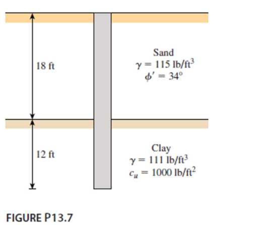
Chapter 13, Problem 13.7P
A 3 ft diameter straight drilled shaft is shown in Figure P13.7. Determine the load-carrying capacity of the drilled shaft with FS = 3. Take
Expert Solution & Answer

Trending nowThis is a popular solution!

Students have asked these similar questions
A free-headed drilled shaft, shown in Figure 4, has an elastic modulus, Ep = 20,000 MPa.
M, = 880 kN m
Q = 245 kN,
Sand
at = 19 kN/m3
O' = 34°
1.2 m
Figure 4
(a) Determine the ground line deflection, x.
Figure P10.7 shows a drilled shaft without a bell. Assume the following values:L1 = 6 m cu(1) = 50 kN/m2L2 = 7 m cu(2) = 75 kN/m2Ds = 1.5 mDetermine:a. The net ultimate point bearing capacity [use Eqs. (10.33) and (10.34)]b. The ultimate skin friction [use Eqs. (10.37) and (10.39)]c. The working load Qw (factor of safety = 3)
Refer to Figure 11.26b. For the drilled shaft with bell, given:Thickness of active zone, Z = 9 mDead load = 1500 kN Live load = 300 kNDiameter of the shaft, Ds = 1 mZero swell pressure for the clay in the active zone = 600 kN/m2Average angle of plinth-soil friction, Φ'ps = 20°Average undrained cohesion of the clay around the bell = 150 kN/m2. Determine the diameter of the bell, Db. A factor of safety of 3 against uplift is required with the assumption that dead load plus live load is equal to zero.
Chapter 13 Solutions
Bundle: Principles Of Foundation Engineering, 9th + Mindtap Engineering, 1 Term (6 Months) Printed Access Card
Ch. 13 - Prob. 13.1PCh. 13 - Prob. 13.2PCh. 13 - Prob. 13.3PCh. 13 - Determine the ultimate load-carrying capacity of...Ch. 13 - For the same data given in Problem 13.4, determine...Ch. 13 - Prob. 13.6PCh. 13 - A 3 ft diameter straight drilled shaft is shown in...Ch. 13 - Prob. 13.8PCh. 13 - Figure P13.9 shows a drilled shaft extending into...Ch. 13 - A free-headed drilled shaft is shown in Figure...
Knowledge Booster


Learn more about
Need a deep-dive on the concept behind this application? Look no further. Learn more about this topic, civil-engineering and related others by exploring similar questions and additional content below.Similar questions
- Figure P13.9 shows a drilled shaft extending into clay shale. Given: qu (clay shale) = 1.81 MN/m2. Considering the socket to be rough, estimate the allowable load-carrying capacity of the drilled shaft. Use FS = 4. Use the Zhang and Einstein procedure.arrow_forwardFor the drilled shaft described in Problem 19.7, estimate the total elastic settlement at working load. Use Eqs. (18.45), (18.47), and (18.48). Assume that Ep = 20 106 kN/m2, s = 0.3, Es = 12 103 kN/m2, = 0.65 and Cp = 0.03. Assume 80% mobilization of skin resistance at working load. (See Part c of Problem 19.7) 19.7 Figure 19.16 shows a drilled shaft without a bell. Here, L1 = 6 m, L2 = 7 m, Ds = 1.5 m, cu(1) = 50 kN/m2, and cu(2) = 75 kN/m2. Find these values: a. The net ultimate point bearing capacity. Use Eqs. (19.23) and (19.24) b. The ultimate skin resistance. Use Eqs. (19.26) and (19.28) c. The working load, Qw (FS = 3) FIG. 19.16arrow_forwardDetermine the ultimate load-carrying capacity of the drilled shaft shown in Figure P13.4, using the Reese and ONeill (1989) method.arrow_forward
- For the drilled shaft described in Problem 19.7, determine these values: a. The ultimate load-carrying capacity b. The load-carrying capacity for a settlement of 25 mm Use the procedure outlined in Section 19.8. 19.7 Figure 19.16 shows a drilled shaft without a bell. Here, L1 = 6 m, L2 = 7 m, Ds = 1.5 m, cu(1) = 50 kN/m2, and cu(2) = 75 kN/m2. Find these values: a. The net ultimate point bearing capacity. Use Eqs. (19.23) and (19.24) b. The ultimate skin resistance. Use Eqs. (19.26) and (19.28) c. The working load, Qw (FS = 3) FIG. 19.16arrow_forwardA drilled shaft designed in accordance with the AASHTO code must support the following downward and uplift axial design loads: P = 850 k, Pup. = 270 k. The soil profile consists of: Undrained Shear Strength, s,, (lb/ft²) Depth (ft) Soil Description Unit Weight, y (lb/ft³) N60 0-15 Clayey silt 115 1200 15-35 Silty clay 112 1800 35-55 Sandy silt (nonplastic) 115 24 55-80 Silty sand 124 43 Practice Problems 597 The groundwater is at a depth of 50 ft. Using the AASHTO resistance factors, select a diameter and depth for a single drilled shaft to support these design loads. Use a load factor of 0.9 on the weight of the shaft. Note there are many different diameter-length combinations that would be satisfactory, but select one that you think would be most appropriate.arrow_forwardA drilled shaft constructed in medium sand is shown in the figure below. Given information is: y = 18 kN/m', '= 38°. Sand is medium-density sand, and the average standard penetration number (N60) within 2Ds below the drilled shaft is 19. Using the method proposed by Reese and O'Neill, determine the following: (a) The net allowable point resistance for a base movement of 25 mm. (b) The shaft frictional resistance for a base movement of 25 mm. (c) The total load that can be carried by the drilled shaft for a total base movement of 25 mm. 1 m 11 m 12 m - 2 marrow_forward
- 1. Triaxial compression tests are done on quartzite rocks, the results are shown below. (0₁+03)/2 -964.25 14500 19575 23200 29000 43210 63075 psi (01-03)/2 964.25 14500 18850 21750 26100 35960 48575 psi Comment on the applicability of each of the Mohr-Coulomb, Griffith, and Hoek-Brown criteria for the testing results.arrow_forwardEarth Sciences Downward force is 4000 kg and rotational force is 3000 kg. Contact surface area (cross sectional area) is 100 cm2. Also, the rock sample (diameter: 20 cm) is tested by a uniaxial compressive strength machine and the sample was cracked at 30000 kg. Answer the following questions:a. Find the resultant force acting on the rock formation.b. Find the bearing strength of the rock drilled.c. Can we drill under these circumstances?arrow_forwardA standard penetration test is carried out in sand where the efficiency of the hammer nH =70%. If the measured N-value at 30 ft depth is 24, find N60 and (N1)60. The unit weight of the sand is 115.0 lb/ft3. Assume nB = nS = nR =1.arrow_forward
- Hint: The problem is 10.10 taken from the book " introductory to mining engineering " written by "Howard L.Hartman" A single rectangular opening 10 ft in height is driven in rock having strengths of fc=18000 lb/in2 and ft= 1500 lb/in2. Rock specific gravity is 2.3. The opening is located at a depth of 2000 ft in a stress field of no lateral pressure and has a fillet ratio of 1/6. (a). Determine if the opening will fail when its width is 20 ft ? (b). What is the maximum safe width of the opening?.A single rectangular opening 10 ft (3.0 m) in height is driven in rock having strengths of fc = 18,000 lb/in2 (124 MPa) and ft=1500 lb/in2. (10.3 MPa).Rock specific gravity is 2.3.The opening is located at depth of 2000 ft (610 m) in a stress field of no lateral pressure and has a fillet ratio of 1/6 .a. Determine if the opening will fail when its width is 20 ft (6.1 m).b. Is there any benefit to reducing the width to 10 ft (3.0 m)? To 5 ft (1.5 m)?c. What is the maximum safe width of opening?arrow_forward= A standard penetration test is carried out in sand where the efficiency of the hammer n 50%. If the measured N-value at 7.5 m depth is 20, find Noo and (N₁)60. The unit weight of the sand is = 15 MR = 1 and 18.08 kN/m³. Assume ¹ = 0.95. If you know that: nsarrow_forward
arrow_back_ios
arrow_forward_ios
Recommended textbooks for you
 Principles of Foundation Engineering (MindTap Cou...Civil EngineeringISBN:9781337705028Author:Braja M. Das, Nagaratnam SivakuganPublisher:Cengage Learning
 Principles of Foundation Engineering (MindTap Cou...Civil EngineeringISBN:9781305081550Author:Braja M. DasPublisher:Cengage Learning
 Fundamentals of Geotechnical Engineering (MindTap...Civil EngineeringISBN:9781305635180Author:Braja M. Das, Nagaratnam SivakuganPublisher:Cengage Learning
Principles of Foundation Engineering (MindTap Cou...
Civil Engineering
ISBN:9781337705028
Author:Braja M. Das, Nagaratnam Sivakugan
Publisher:Cengage Learning
Principles of Foundation Engineering (MindTap Cou...
Civil Engineering
ISBN:9781305081550
Author:Braja M. Das
Publisher:Cengage Learning
Fundamentals of Geotechnical Engineering (MindTap...
Civil Engineering
ISBN:9781305635180
Author:Braja M. Das, Nagaratnam Sivakugan
Publisher:Cengage Learning
CE 414 Lecture 02: LRFD Load Combinations (2021.01.22); Author: Gregory Michaelson;https://www.youtube.com/watch?v=6npEyQ-2T5w;License: Standard Youtube License