
EBK LOGIXPRO PLC LAB MANUAL FOR PROGRAM
5th Edition
ISBN: 8220102803503
Author: Petruzella
Publisher: YUZU
expand_more
expand_more
format_list_bulleted
Concept explainers
Videos
Textbook Question
Chapter 13, Problem 14P
The
- a. Examine the ladder logic and describe how the circuit would operate as programmed.
- b. Troubleshoot the program and identify what needs to be changed to have it operate properly.
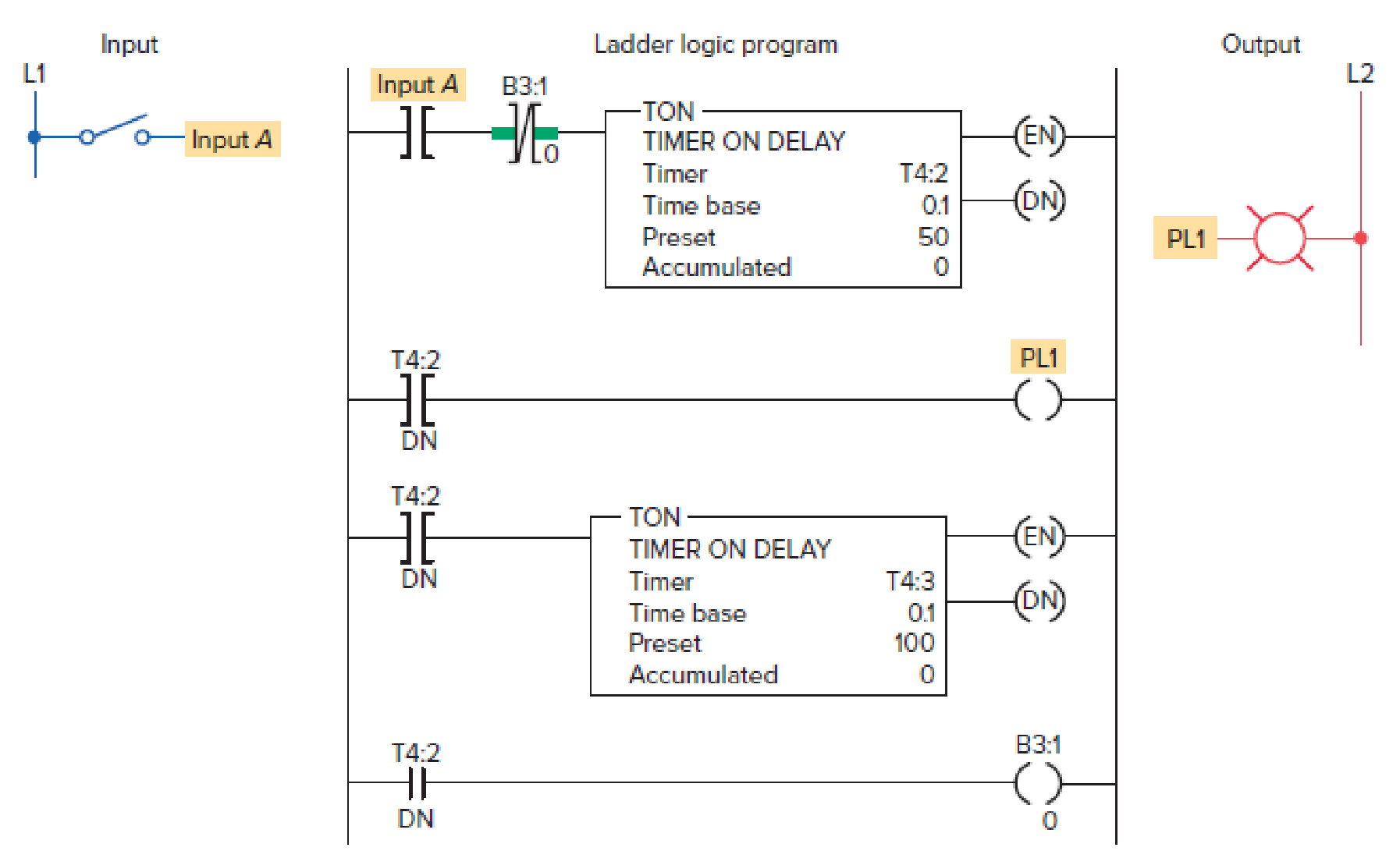
Figure 13-39 Program for Problem 14.
Expert Solution & Answer
Want to see the full answer?
Check out a sample textbook solution
Students have asked these similar questions
Table 3
INPUTS
OUTPUTS
Y
F
A3. Connect the circuit shown in Fig. 4.2. Apply the inputs X and Y in Table 2 with data
switches. Monitor the output with the probe and record the output for each set of inputs in the
F column of Table 2.
1
1
1
1
A6. Construct the expression obtained in A4 by using only NAND gates. Draw and implement
the NAND gates connection diagram of the function. Record the output for each set of inputs
in the F column of Table 4. (Note that A+B = (A'.B')
F
F=
Fig. 4.2
Table 2
INPUTS
OUTPUT
Y
F
Table 4
1
INPUTS
OUTPUTS
1
F
1
1
1
A4. Express the function in Fig. 4.2 as a sum of minterms (sum-of-products) using Table 2.
1
1
F=
Questions (True or False):
# Question
1 All the logic functions can be implemented with only
NAND Gates.
(T/F)
2
A5. Draw the logic circuit of the expression obtained in A4 by using NOT, OR, AND gates.
B
Implement the logical circuit to monitor the output with a probe and record the output for each
set of inputs in the F column of Table 3.
1. Design a logic circuit that has 3 inputs A, B, and Cand one output F. The output of the circuit is to be F = 1if the number of
ones in input variables (ABC) is even, otherwise F=0. Construct the truth table.
2. Fnd the minterm expansion for the combinational circuit represented by the following truth table:
АВСЕ
0000
0011
0100
0111
1001
1011
1100
1111
Use the editor to format your answer
Develop the ladder logic diagram to fill the tank. 1. Filling the water tank up to 80%. When the tank is filled, turn ON the heater to raise the temperature up to 70-degree C.2. when this temperature is reached, turn OFF the heater & open the outlet valve.3. When the level in the tank falls below 10%, closes the output valve and start filling the tank again.4. A digital counter is used to monitor the number of times the tank is emptied (reaches 10%). Once the counter reaches to 8 times, the system is stopped.
Chapter 13 Solutions
EBK LOGIXPRO PLC LAB MANUAL FOR PROGRAM
Ch. 13 - Prob. 1RQCh. 13 - Prob. 2RQCh. 13 - Prob. 3RQCh. 13 - List three potential noise-generating inductive...Ch. 13 - Prob. 5RQCh. 13 - Prob. 6RQCh. 13 - Prob. 7RQCh. 13 - Under what condition can a ground loop circuit be...Ch. 13 - Prob. 9RQCh. 13 - What operating state will cause an inductive load...
Ch. 13 - Prob. 11RQCh. 13 - Prob. 12RQCh. 13 - Prob. 13RQCh. 13 - Prob. 14RQCh. 13 - Prob. 15RQCh. 13 - List four uses for the data monitor function.Ch. 13 - Prob. 17RQCh. 13 - Prob. 18RQCh. 13 - Prob. 19RQCh. 13 - Prob. 20RQCh. 13 - Prob. 21RQCh. 13 - Prob. 22RQCh. 13 - Prob. 23RQCh. 13 - Prob. 24RQCh. 13 - Prob. 25RQCh. 13 - Prob. 26RQCh. 13 - Prob. 27RQCh. 13 - Prob. 28RQCh. 13 - Prob. 29RQCh. 13 - Prob. 30RQCh. 13 - Prob. 1PCh. 13 - A fuse is blown in an output module. Suggest two...Ch. 13 - Prob. 3PCh. 13 - Prob. 4PCh. 13 - Prob. 5PCh. 13 - Prob. 6PCh. 13 - A specific output is forced on, but the LED module...Ch. 13 - An electronic-based input sensor is wired to a...Ch. 13 - Prob. 9PCh. 13 - Prob. 11PCh. 13 - Prob. 12PCh. 13 - Prob. 13PCh. 13 - The program of Figure 13-39 is supposed to execute...
Knowledge Booster


Learn more about
Need a deep-dive on the concept behind this application? Look no further. Learn more about this topic, computer-science and related others by exploring similar questions and additional content below.Similar questions
- Computer Science 1. Design a circuit for a digital lock using the minimum number of D latches. The lock has two input push-button switches A, B and it outputs a single pulse (Z1) for each activation i.e. lock open. The two switches are interlocked mechanically so that simultaneous pulses are not possible. The lock should have the following features: a. The opening sequence is 0011. ii. Then replace ‘0’ by ‘A’ and ‘1’ by ‘B’ in the sequence. b. Five B pulses should give an absolute reset. c. Any incorrect use of the A switch will cause an output (Z2) to ring a bell to warn that the lock is being tampered.arrow_forward= 0, Design a sequential circuit with two D flip-flops A and B, and one input x_in. When x_in the state of the circuit remains the same. When x in = 1, the circuit goes through the state transitions from 00 to 01, to 11, to 10, back to 00, and repeats.arrow_forwardIV. PROCEDURES: For the AND gate look on the data sheets, connect the circuit on Breadboard and test the gate. Using logic switches SW1 and SW2, apply the logic levels 0 and 1 to gate inputs Create a truth table and record the results Also simulate the given gate using the Circuit Wizard simulation software Obtain the corresponding circuit diagram using the simulation software of the Boolean expression F((A,B,C)= АВ* AC * ВС From the obtain circuit diagram develop the corresponding truth table From the figure below obtain the equivalent Boolean expression and develop its corresponding truth Table АП сПо- Boolean Expression: Z= (AB)(CD)arrow_forward
- Design a sequential circuit with two T flip-flops A and B and two inputs E and F and a reset which will satisfy the following design requirements. If E=0, the circuit remains in the same state regardless of the value of F. When E=1 and F=1, the circuit goes through the state transitions from 00 to 01, to 10, to 11, back to 00, and repeats. When E=1 and F=0, the circuit goes through the state transitions from 00 to 11, to 10, to 01, back to 00, and repeats. The results should be consistent with the simulation timing diagrams shown below. 1. Draw a state diagram for this requirement using the template below. 2. Draw a present state / next state table for this requirement using the template below. 3. Use Karnaugh maps to determine the flip flop minimized Boolean input expressions. 4. Model the design requirement using Verilog structural source code. Use T flip- flops. Provide the source code. 5. Simulate the structural model using a test bench with stimulus test signals as shown in the…arrow_forward4. Design a combinational circuit with three inputs x, y, z and three outputs A, B, C. The output is equal to 0 when the input variable has more 1's than 0's and the output is equal to 1 more than the binary input whose input variables have more 0's than 1's. Fill the values in the truth table and draw the logic diagram (few values are filled for reference) X 0 0 0 0 1 1 1 1 y 0 0 1 1 0 0 1 1 Z 0 1 0 1 0 1 0 1 DB = A'x DA = (AX+BX) A 0 0 B 0 0 5. Design a sequential circuit with two D flip-flops A and B, input x and output Y. The flip-flop input equations and the circuit output equations are as follows: C 1 Y = (A+B)x (Draw the circuit diagram and state table) 0arrow_forward4. Design a combinational circuit with three inputs x, y, z and three outputs A, B, C. The output is equal to 0 when the input variable has more 1's than 0's and the output is equal to 1 more than the binary input whose input variables have more 0's than 1's. Fill the values in the truth table and draw the logic diagram (few values are filled for reference) X 0 0 0 0 1 1 1 1 y 0 0 1 1 0 0 1 1 Z 0 1 0 1 0 1 0 1 A 0 0 B 0 0 C 1 0arrow_forward
- 1. Design the state diagram and create the state table for a synchronous to detect the sequence 0101. The circuit has a single input, x, and a single output z. The output is logic-1 whenever the input sequence 0101 is detected, logic-0 otherwise. Note that overlapping sequences are allowed (that is: If the input is 01010101, the output is high on every 1 beginning with the second). Write the equations for the state variables and the output z ?arrow_forwardQuestion: A logic circuit has 4 inputs and an output. The Output will be high for binary input combinations of only your last 3 digits (Highlighted) of your ID. For example, if your ID is: 20-43460-1 then output will be high only for binary input combinations of 4, 6 and 0. Now, a) Construct a truth table for the system. b) Write SOP expression and POS expression from the truth table. c) Find standardized SOP expression and standardized POS expression for the system. d) Find the simplified expression using Boolean algebra and De-Morgan's theorem. e) Find simplified expression using Karnaugh-Map. f) Design the most simplified expression using basic gates. g) Design the most simplified expression using both the universal gates. h) Design the most simplified expression using RTL logic. i) Design the most simplified expression using DTL logic.arrow_forwardDesign a circuit where each time PB1 is pressed and released output Q1 turns on for 1 seconds, off for 1 seconds, on for 2 second and then stops.arrow_forward
- Question 1 Implement the following logic functions using BJTs. Use the S-Model. Both input and output should be voltage signals OUT= A.B + C OUT = A.B + A.Barrow_forwardPROGRAMMABLE LOGIC CONTROLLERSarrow_forward60. Energy equation of pulse of the logic transition, can be computed as a. Energydynamic ? Capacitive load b. Energydynamic 1/? Capacitive load c. Energydynamic ? Capacitive load - Voltage2 d. Energydynamic ? Capacitive load + Voltage2arrow_forward
arrow_back_ios
SEE MORE QUESTIONS
arrow_forward_ios
Recommended textbooks for you
 Database System ConceptsComputer ScienceISBN:9780078022159Author:Abraham Silberschatz Professor, Henry F. Korth, S. SudarshanPublisher:McGraw-Hill Education
 Starting Out with Python (4th Edition)Computer ScienceISBN:9780134444321Author:Tony GaddisPublisher:PEARSON
 Digital Fundamentals (11th Edition)Computer ScienceISBN:9780132737968Author:Thomas L. FloydPublisher:PEARSON
 C How to Program (8th Edition)Computer ScienceISBN:9780133976892Author:Paul J. Deitel, Harvey DeitelPublisher:PEARSON
 Database Systems: Design, Implementation, & Manag...Computer ScienceISBN:9781337627900Author:Carlos Coronel, Steven MorrisPublisher:Cengage Learning
 Programmable Logic ControllersComputer ScienceISBN:9780073373843Author:Frank D. PetruzellaPublisher:McGraw-Hill Education
Database System Concepts
Computer Science
ISBN:9780078022159
Author:Abraham Silberschatz Professor, Henry F. Korth, S. Sudarshan
Publisher:McGraw-Hill Education
Starting Out with Python (4th Edition)
Computer Science
ISBN:9780134444321
Author:Tony Gaddis
Publisher:PEARSON
Digital Fundamentals (11th Edition)
Computer Science
ISBN:9780132737968
Author:Thomas L. Floyd
Publisher:PEARSON
C How to Program (8th Edition)
Computer Science
ISBN:9780133976892
Author:Paul J. Deitel, Harvey Deitel
Publisher:PEARSON
Database Systems: Design, Implementation, & Manag...
Computer Science
ISBN:9781337627900
Author:Carlos Coronel, Steven Morris
Publisher:Cengage Learning
Programmable Logic Controllers
Computer Science
ISBN:9780073373843
Author:Frank D. Petruzella
Publisher:McGraw-Hill Education
Tutorial: Photoconductivity; Author: MIT OpenCourseWare;https://www.youtube.com/watch?v=20GlFVyxqHY;License: Standard YouTube License, CC-BY
photoconductive cell; Author: Electronics Engineering;https://www.youtube.com/watch?v=Bxo3v_5QGaA;License: Standard Youtube License