
Shigley's Mechanical Engineering Design (McGraw-Hill Series in Mechanical Engineering)
10th Edition
ISBN: 9780073398204
Author: Richard G Budynas, Keith J Nisbett
Publisher: McGraw-Hill Education
expand_more
expand_more
format_list_bulleted
Concept explainers
Videos
Textbook Question
Chapter 13, Problem 25P
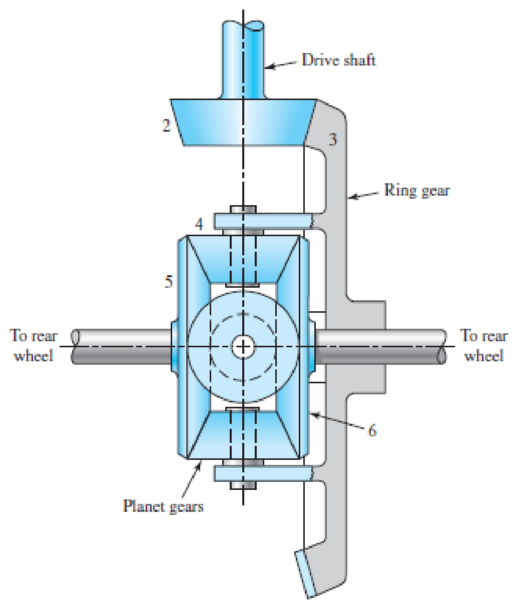
The tooth numbers for the automotive differential shown in the figure are N2 = 16, N3 = 48, N4 = 14, N5 = N6 = 20. The drive shaft turns at 900 rev/min.
- (a) What are the wheel speeds if the car is traveling in a straight line on a good road surface?
- (b) Suppose the right wheel is jacked up and the left wheel resting on a good road surface. What is the speed of the right wheel?
- (c) Suppose, with a rear-wheel drive vehicle, the auto is parked with the right wheel resting on a wet icy surface. Does the answer to part (b) give you any hint as to what would happen if you started the car and attempted to drive on?
Problem 13-25
Expert Solution & Answer
Want to see the full answer?
Check out a sample textbook solution
Students have asked these similar questions
The double-reduction helical gearset shown in the figure is driven through shaft a at a speed of 700 rev/min. Gears 2 and 3 have a normal diametral pitch of 12 teeth/in, a 30° helix angle, and a normal pressure angle of 20°. The second pair of gears in the train, gears 4 and 5, have a normal diametral pitch of 8 teeth/in, a 25° helix angle, and a normal pressure angle of 20°.
The tooth numbers are: N, = 12, N, = 48, N4 = 16, N, = 36. Find:
(a) The directions of the thrust force exerted by each gear upon its shaft
(b) The speed and direction of shaft c
(c) The center distance between shafts
An epicyclic gear shown in figure below consists of ring gear, planet gear and sun gear. The ring gear has 72 internal teeth and sun gear has 32 external teeth. Planet gear meshes with both ring and sun gears and is carried on an arm which rotates about the centre of the ring gear at 20 r.p.m. If the gear A is fixed,
Calculate the speed of plane gear.
In the fabric dye-printing system given in the figure, the motion is transmitted from the electric motor to the drum of the machine. There is a two-stage reducer in between. Number of teeth of gears z1=17; z2=85; z3=18; z4=72; The efficiency of a pair of gears is given as na=0.97 and the efficiency of each of the gearbox shafts and lower bearing pairs to the drum bearing is given as n=0.97.
The diameter of the drum will be D=200 mm, the fabric speed will be v=1 m/s and the pulling force required to activate the band will be taken as F-2000 N.
a) Find the number of revolutions of the engine. b) Find the required engine power.
Chapter 13 Solutions
Shigley's Mechanical Engineering Design (McGraw-Hill Series in Mechanical Engineering)
Ch. 13 - A 17-tooth spur pinion has a diametral pitch of 8...Ch. 13 - A 15-tooth spur pinion has a module of 3 mm and...Ch. 13 - A spur gearset has a module of 6 mm and a velocity...Ch. 13 - A 21-tooth spur pinion mates with a 28-tooth gear....Ch. 13 - A 20 straight-tooth bevel pinion having 14 teeth...Ch. 13 - A parallel helical gearset uses a 20-tooth pinion...Ch. 13 - A parallel helical gearset consists of a 19-tooth...Ch. 13 - To avoid the problem of interference in a pair of...Ch. 13 - Prob. 9PCh. 13 - Prob. 10P
Ch. 13 - Prob. 11PCh. 13 - Prob. 12PCh. 13 - Prob. 13PCh. 13 - Prob. 14PCh. 13 - A parallel-shaft gearset consists of an 18-tooth...Ch. 13 - The double-reduction helical gearset shown in the...Ch. 13 - Shaft a in the figure rotates at 600 rev/min in...Ch. 13 - The mechanism train shown consists of an...Ch. 13 - The figure shows a gear train consisting of a pair...Ch. 13 - A compound reverted gear trains are to be designed...Ch. 13 - Prob. 21PCh. 13 - Prob. 22PCh. 13 - Prob. 23PCh. 13 - A gearbox is to be designed with a compound...Ch. 13 - The tooth numbers for the automotive differential...Ch. 13 - Prob. 26PCh. 13 - In the reverted planetary train illustrated, find...Ch. 13 - Prob. 28PCh. 13 - Tooth numbers for the gear train shown in the...Ch. 13 - The tooth numbers for the gear train illustrated...Ch. 13 - Shaft a in the figure has a power input of 75 kW...Ch. 13 - The 24T 6-pitch 20 pinion 2 shown in the figure...Ch. 13 - The gears shown in the figure have a module of 12...Ch. 13 - The figure shows a pair of shaft-mounted spur...Ch. 13 - Prob. 35PCh. 13 - Prob. 36PCh. 13 - A speed-reducer gearbox containing a compound...Ch. 13 - For the countershaft in Prob. 3-72, p. 152, assume...Ch. 13 - Prob. 39PCh. 13 - Prob. 40PCh. 13 - Prob. 41PCh. 13 - Prob. 42PCh. 13 - The figure shows a 16T 20 straight bevel pinion...Ch. 13 - The figure shows a 10 diametral pitch 18-tooth 20...Ch. 13 - Prob. 45PCh. 13 - The gears shown in the figure have a normal...Ch. 13 - Prob. 47PCh. 13 - Prob. 48PCh. 13 - Prob. 49PCh. 13 - The figure shows a double-reduction helical...Ch. 13 - A right-hand single-tooth hardened-steel (hardness...Ch. 13 - The hub diameter and projection for the gear of...Ch. 13 - A 2-tooth left-hand worm transmits 34 hp at 600...
Knowledge Booster


Learn more about
Need a deep-dive on the concept behind this application? Look no further. Learn more about this topic, mechanical-engineering and related others by exploring similar questions and additional content below.Similar questions
- A compound epicyclic gear is shown in Fig. for Q.2. C and D form acompound wheel which rotates freely on shaft G. The planet wheels B andE rotate on pins fixed in arms attached to shaft G. C and F have internalteeth: the others have external teeth with the following numbers: A, 40;B, 30; D, 50; E, 20. If A rotates at 500 rev/min and wheel F is fixed,find the speed of shaft G.arrow_forwardIn the Scottish Yoke mechanism in the figure, r = 63 cm, φ = 23 °, β = 116 ° and e = 34 cm are given. Accordingly, find the velocity of the S3 output since the angular velocity of the actuating limb is θ = 0.14 rad / s. Partial scoring; S3 50% in cmarrow_forwardpinion having 20 involute teeth of module pitch 6 mm rotates at 200 r.p.m. and transmits 1.5 kW to a gear wheel having 50 teeth. The addendum on both the wheels is 1/4 of the circular pitch. The angle of obliquity is 20°. Find (a) the length of the path of approach ; (b) the length of the arc of approach; (c) the normal force between the teeth at an instant where there is only pair of teeth in contact.arrow_forward
- Shaft "a" in the figure rotates at 450 rev/min in the direction shown. Find the speed and direction of rotation of shaft "d".arrow_forwardShaft a in the figure has a power input of 75 kW at a speed of 1000 rev/min in the counterclockwise direction. The gears have a module of 5 mm and a 20° pressure angle. Gear 3 is an idler (b) Find the torque T4c that gear 4 exerts on shaft c.arrow_forwardA 220 mm diameter of 14.5 degrees involute gear is used to transmit 50 kW at 580 rpm Find the total force transmitted on the gear.arrow_forward
- In the pulley system shown in the figure, while the P gear rotates in the direction of 1 with its angular velocity, find the direction and angular velocity values of the other gears. Hint: The speed of the gears is equal at the point of contact. The speed of a belt is the same at all points.( w=3 rad/s , rk=0.8m ,rL=0.2 m ,rM=0.2m, rN=0.5m rP=0.4m rR=0.4marrow_forwardAs seen in the figure, a construction machine is rotated by a drive mechanism consisting of belt-pulley and spur gear mechanisms. Engine power P = 5.5 kW ; engine shaft speednm = 1500 rpm ; drive pulley diameter Dt = 16 cm ; diameter of the opposite pulley Dk = 55 cm ; number of pinion teeth z1 = 21 ; number of teeth of the counter gearz2 = 60 ; pulley mechanism efficiency ηk = 0.95 ; Since the efficiency of the gear mechanism is ηd = 0.97: a) Find the output shaft speed nç and the torque Mç on this shaft.b) The force on the taut arm of the belt S1 = 450 N;coefficient of friction μ = 0.3 ; If the winding angle α = 160⁰, is the frictionally transmitted moment Ms sufficient to compensate for the Mg moment on the input shaft? Calculate.arrow_forwardA gear train is composed of four helical gears with the three shaft axes in a single plane, as shown in the figure. The gears have a normal pressure angle of 20 and a 30 helix angle. Gear is the driver, and is rotating counterclockwise as viewed from the top. Shaft b is an idler and the transmitted load from gear 2 to gear 3 is 500 Ibf. The gears on shaft b both have a normal diametral pitch of 7 teeth/in and have 54 and 14 teeth, respectively. Find the forces exerted by gears 3 and 4 on shaft barrow_forward
- The diameters of the solid shafts in the gear wheel set shown in the figure are dAB = 20mm, dCD = 25mm, dEF = 40mm. Since the safety shear stress of each shaft is 90MPa, determine the largest T torque that can be applied. Calculate the total angle of rotation in A for the maximum applied torque value.arrow_forwardThe four helical gears shown in figure have a module in the normal plane of 4 mm and a pressure angle in the normal plane of 0.35 rad. The motor shaft rotates 550 rpm and transmits 20 kW. Other data are on the drawing. (a) What is the speed ratio between the motor (input) and output shafts? (b) Determine all force components that the 20-tooth pinion applies to the 50-tooth gear. Make a sketch showing these forces applied to the gear. (c) The same as part (b), except for the force components that the 50-tooth gear exerts on the 25- tooth pinion 100 50 teeth 200 125 25 teeth ψ = 0.35 rad right hand Motor 20 teeth ψ = 0.50 rad left hand 50 teeth Outputarrow_forwardA spur pinion of pitch diameter 50 mm rotates at 200 rad/s and transmits 3 kW power. The pressure angle of the tooth of the pinion is 20°. find the total force exerted by a tooth of the pinion on other gear?arrow_forward
arrow_back_ios
SEE MORE QUESTIONS
arrow_forward_ios
Recommended textbooks for you
 Elements Of ElectromagneticsMechanical EngineeringISBN:9780190698614Author:Sadiku, Matthew N. O.Publisher:Oxford University Press
 Mechanics of Materials (10th Edition)Mechanical EngineeringISBN:9780134319650Author:Russell C. HibbelerPublisher:PEARSON
 Thermodynamics: An Engineering ApproachMechanical EngineeringISBN:9781259822674Author:Yunus A. Cengel Dr., Michael A. BolesPublisher:McGraw-Hill Education
 Control Systems EngineeringMechanical EngineeringISBN:9781118170519Author:Norman S. NisePublisher:WILEY
 Mechanics of Materials (MindTap Course List)Mechanical EngineeringISBN:9781337093347Author:Barry J. Goodno, James M. GerePublisher:Cengage Learning
 Engineering Mechanics: StaticsMechanical EngineeringISBN:9781118807330Author:James L. Meriam, L. G. Kraige, J. N. BoltonPublisher:WILEY
Elements Of Electromagnetics
Mechanical Engineering
ISBN:9780190698614
Author:Sadiku, Matthew N. O.
Publisher:Oxford University Press
Mechanics of Materials (10th Edition)
Mechanical Engineering
ISBN:9780134319650
Author:Russell C. Hibbeler
Publisher:PEARSON
Thermodynamics: An Engineering Approach
Mechanical Engineering
ISBN:9781259822674
Author:Yunus A. Cengel Dr., Michael A. Boles
Publisher:McGraw-Hill Education
Control Systems Engineering
Mechanical Engineering
ISBN:9781118170519
Author:Norman S. Nise
Publisher:WILEY
Mechanics of Materials (MindTap Course List)
Mechanical Engineering
ISBN:9781337093347
Author:Barry J. Goodno, James M. Gere
Publisher:Cengage Learning
Engineering Mechanics: Statics
Mechanical Engineering
ISBN:9781118807330
Author:James L. Meriam, L. G. Kraige, J. N. Bolton
Publisher:WILEY
Power Transmission; Author: Terry Brown Mechanical Engineering;https://www.youtube.com/watch?v=YVm4LNVp1vA;License: Standard Youtube License