
Concept explainers
Videos
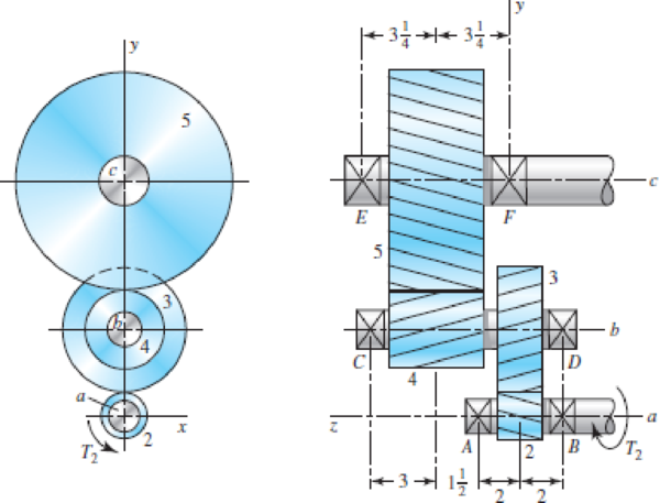
The figure shows a double-reduction helical gearset. Pinion 2 is the driver, and it receives a torque of 1200 lbf · in from its shaft in the direction shown. Pinion 2 has a normal diametral pitch of 8 teeth/in, 14 teeth, and a normal pressure angle of 20° and is cut right-handed with a helix angle of 30°. The mating gear 3 on shaft b has 36 teeth. Gear 4, which is the driver for the second pair of gears in the train, has a normal diametral pitch of 5 teeth/in, 15 teeth, and a normal pressure angle of 20° and is cut left-handed with a helix angle of 15°. Mating gear 5 has 45 teeth. Find the magnitude and direction of the force exerted by the bearings C and D on shaft b if bearing C can take only a radial load while bearing D is mounted to take both radial and thrust loads.
Problem 13–50
Dimensions in inches.
The magnitude and direction of the force exerted by the bearing
The magnitude and direction of the force exerted by the bearing
Answer to Problem 50P
The magnitude and direction of the force exerted by the bearing
The magnitude and direction of the force exerted by the bearing
Explanation of Solution
The figure below shows the forces acting on the assembly of gears on the shaft
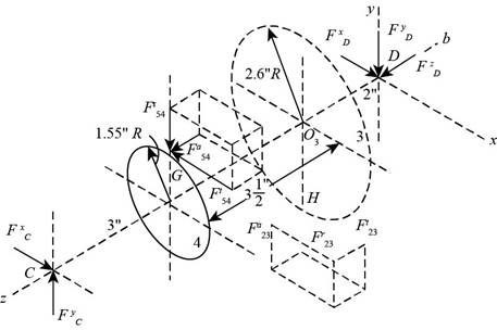
Figure-(1)
The center of the gear 3 is
Write the expression for the diameter of the gear 2.
Here, the number of teeth on the gear 2 is
Write the expression for the diameter of the gear 4.
Here, the number of teeth on the gear 2 is
Write the expression for the diameter of the gear 3.
Here, the number of teeth on the gear 3 is
Write the expression for the diameter of the gear 5.
Here, the number of teeth on the gear 5 is
Write the expression for the transverse pressure angle for gears 2.
Here, the normal pressure angle is
The transverse pressure angle for gears 2 and 3 are same.
Write the expression for the transverse pressure angle for gears 4.
Here, the normal pressure angle is
Write the expression for the tangential force on the gear 3.
Here, the torque on the gear 2 is
Write the expression for the radial force on the gear 3.
Write the expression for the axial force on the gear 3.
Calculate the tangential load on the gear 4.
Write the expression for the radial force on the gear 4.
Write the expression for the axial force on the gear 4.
Write the expression for the position vector for
Here, the length of
Write the expression for the position vector for
Here, the length of
Write the expression for the position vector for
Here, the length of
Write the expression for the force
Write the expression for the force
Write the expression for the force on the bearing
Write the expression for the force on the bearing
Write the expression for the moment at
Substitute
Write the expression for the force balance equation.
Conclusion:
Substitute
Substitute
Substitute
Substitute
Substitute
Substitute
Substitute
Substitute
Substitute
Substitute
Substitute
Substitute
Substitute
Further simplification,
Compare the
Compare the
Substitute
Substitute
Substitute
Substitute
Further simplification.
Compare the
Compare the
Compare the
Substitute
Thus, the force in the bearing
Substitute
Thus, the magnitude and direction of the force exerted by the bearing
Want to see more full solutions like this?
Chapter 13 Solutions
Shigley's Mechanical Engineering Design (McGraw-Hill Series in Mechanical Engineering)


- Two meshing spur gears with 20° pressure angle have a module of 4 mm. The centre distance is 220 mm andthe number ofteethonthe pinionis 40. What shouldbethe new centre distance so that pressure angle is increased to 22°?arrow_forwardProvide the complete step-by-step solution, given data, conversion of units, and sketch for this problem. A turbine at 30,000 rpm is used to drive a reduction gear delivering 3 hp at 3,000rpm. The gears are 20 degrees involute herringbone gears of 28 pitch and 2 1/8 ineffective width. The pinion has 20 teeth with a helix angle of 23 deg. Determine theload normal to the tooth surface. A. 20.4 lbs B. 24.4 lbs C. 28.4 lbs D. 32.4arrow_forwardA simple gear train of 30 and 50 teeth for pinion and gear wheel respectively,is used to drive an electric wheelchair at a velocity that is double the maximum velocity of slip. The pinion has an equal addendum as the gear wheel, a module of 3 mm, and a pressure angle of 14.5o. The wheelchair has a maximum velocity of 5 m/s when its pinion rotates at 800 r.p.m. Calculate: 1.1. The magnitude of the velocity of slip of gears in mesh. (2)1.2. The angular speed of the gear wheel in rad/s. (4)1.3. The maximum length of a path of the approach in mm. (2)1.4. The length of a path of a recess in mm. (7)1.5. The addendum of the gears in mm. (7)1.6. The contact ratio.arrow_forward
- The parallel shafts are connected with two full depth spur gears, with a pinion module of 4 mm. The pressure angle is 25 degree. The number of teeth of the gear is 52. The angular speed ratio is desired as 2,6. Calculate the pitch line velocity (m/s) where the angular speed of the pinion is 2600 rev/min.arrow_forwardTwo straight-toothed bevel gears mesh with a shaft angle of 90° and a diametral pitch of 5. The pinion has 20 teeth, and the gear ratio is 2:1. The addendum and dedendum are the same as for 20 stub teeth. For the gear, determine the pitch radius, cone angle, outside diameter, cone distance, and face width.arrow_forwardFor a pair of standard gears, the module is m=2.5mm,pressure angle is α=20 0. ha*=1. c*=0.25. The teeth number on gear 1 is z1=22. The standard center distance is a=68.75mm. Calculate the contact ratio ε with the standard center distance a, 68.75mm. ε=( )arrow_forward
- A 17-tooth 20° pressure angle spur pinion rotates at 1800 rev/min and transmits 4 hp to a 52-tooth disk gear. The diametral pitch is 10 teeth/in, the face width 1.5 in, and the quality standard is No. 6. The gears are straddle-mounted with bearings immediately adjacent. The pinion is a grade 1 steel with a hardness of 240 Brinell tooth surface and through-hardened core. The gear is steel, through-hardened also, grade 1 material, with a Brinell hardness of 200, tooth surface and core. Poisson's ratio is 0.30, Jp = 0.30, JG = 0.40, and Young's modulus is 30(10°) psi. The loading is smooth because of motor and load. Assume a pinion life of 108 cycles and a reliability of 0.90, and use YN = 1.3558N-0.0178, ZN = 1.4488N-0.023. The tooth profile is uncrowned. This is a commercial enclosed gear unit. (a) Find the factor of safety of the gears in bending. (b) Find the factor of safety of the gears in wear. (c) By examining the factors of safety, identify the threat to each gear and to the…arrow_forwardA simple gear train of 30 and 50 teeth for pinion and gear wheel respectively, is used to drive an electric wheelchair at a velocity that is double the maximum velocity slip. The pinion has an equal addendum as the gear wheel, a module of 3 mm, and a pressure angle of 14,5. The wheelchair has a maximum velocity of 5 m/s when it's pinion rotates at 800 rpm. Calculate : 1.1)The magnitude of the velocity of slip of gears in mesh 1.2)The angular speed of the gear wheel in rad/s 1.3)The maximum length of a path of the approach in mm 1.4)The length of a path of a recess in mm. 1.5) The addendum of the gears in mm. 1.6) The contact ratioarrow_forwardQuestion 1 A pickup truck is driving at a speed of 100 km/h on a leveled road. This truck has4 wheels of the same diameter of 400 mm and drives at a gear ratio of 5 to 1 if its gearbox 5th gear is selected. The gear’s teeth are of involute form with a module of 8 mm, an addendum is double the module, and the pressure angle is equal to 20°. 1(a). If the driving shaft of the front wheels of the truck is connected to the output shaft of the gearbox, determine the number of teeth on the pinion to avoid interference and the corresponding number of teeth on the gear wheel. 1(b) Calculate the gear maximum velocity of sliding.arrow_forward
- A pair of gray iron and steel helical gears, having a helix angle of 15° with 20° full-depth teeth are to transmit 10 hp at 1500 rpm of a 4-in pinion having a total number of 28teeth. The velocity ratio desired is about mw = 4. Find the (a) normal circular pitch, (b) normal diametral pitch, (c) axial pitch, and (d) dynamic loadarrow_forwardA pair of gray iron and steel helical gears, having a helix angle of 15° with 20° full-depth teeth are to transmit 10 hp at 1500 rpm of a 4-in pinion having a total number of 28teeth. The velocity ratio desired is about mw = 4. Find the (a) normal circular pitch, (b) normal diametral pitch, (c) axial pitch, and (d) dynamic loaarrow_forwardDesign a two-stage compound spur gear train for an overall ratio of approximately 17+ID:1. Specify tooth numbers for each gear in the train. ID=007arrow_forward
 Elements Of ElectromagneticsMechanical EngineeringISBN:9780190698614Author:Sadiku, Matthew N. O.Publisher:Oxford University Press
 Mechanics of Materials (10th Edition)Mechanical EngineeringISBN:9780134319650Author:Russell C. HibbelerPublisher:PEARSON
 Thermodynamics: An Engineering ApproachMechanical EngineeringISBN:9781259822674Author:Yunus A. Cengel Dr., Michael A. BolesPublisher:McGraw-Hill Education
 Control Systems EngineeringMechanical EngineeringISBN:9781118170519Author:Norman S. NisePublisher:WILEY
 Mechanics of Materials (MindTap Course List)Mechanical EngineeringISBN:9781337093347Author:Barry J. Goodno, James M. GerePublisher:Cengage Learning
 Engineering Mechanics: StaticsMechanical EngineeringISBN:9781118807330Author:James L. Meriam, L. G. Kraige, J. N. BoltonPublisher:WILEY