
Concept explainers
Videos
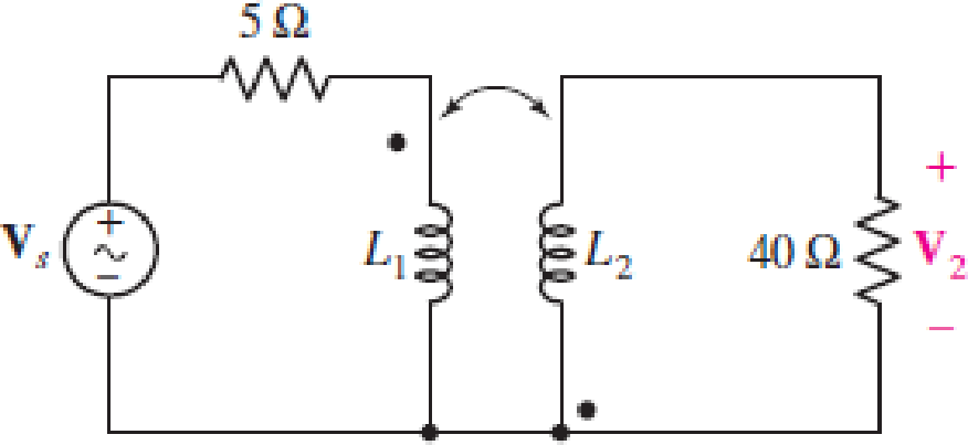
Obtain an expression for V2/Vs in the circuit of Fig. 13.68 if (a) L1 = 100 mH, L2 = 500 mH, and M is its maximum possible value; (b) L1 = 5L2 = 1.4 H and k = 87% of its maximum possible value; (c) the two coils can be treated as an ideal transformer, the left-hand coil having 500 turns and the right-hand coil having 10,000 turns.
FIGURE 13.68
(a)
Find the expression for
Answer to Problem 54E
The expression for
Explanation of Solution
Given data:
Refer to Figure 13.68 in the textbook for the given circuit.
The circuit parameters are given as follows:
Formula used:
Write the expression for reactance due to inductive coil of self-inductance as follows:
Here,
Write the expression for reactance due to inductive coil of mutual-inductance as follows:
Here,
Write the expression for mutual inductance as follows:
Here,
Calculation:
The maximum possible value of
Substitute 1 for
Observer the dot notation in the circuit, use the expression in Equations (1), (2), and apply KVL to the primary winding-loop in the given circuit as follows:
Simplify the expression as follows:
Substitute
Observer the dot notation, use the expression in Equations (1), (2), and apply KVL to the secondary winding-loop in the given circuit as follows:
Substitute
Substitute
From the given circuit, write the expression for
Rearrange the expression as follows:
Substitute
Rearrange the expression as follows:
Conclusion:
Thus, the expression for
(b)
Find the expression for
Answer to Problem 54E
The expression for
Explanation of Solution
Given data:
The circuit parameters are given as follows:
Calculation:
Find the value of
Substitute 0.87 for
Substitute 1.4 H for
Substitute 0.28 H for
Substitute
Substitute
Rearrange the expression as follows:
Conclusion:
Thus, the expression for
(c)
Find the expression for
Answer to Problem 54E
The expression for
Explanation of Solution
Given data:
The circuit parameters are given as follows:
Formula used:
Write the expression for transformer ratio as follows:
Here,
Write the expression for input impedance of the transformer as follows:
Here,
From the given circuit, write the expression for current through primary winding of the transformer as follows:
Calculation:
Substitute 500 for
Substitute 20 for
Substitute
From the given circuit, write the expression for
From Equation (12), substitute
Write the expression for transformer ratio in terms of voltages as follows:
Substitute 20 for
Rearrange the expression as follows:
Conclusion:
Thus, the expression for
Want to see more full solutions like this?
Chapter 13 Solutions
Loose Leaf for Engineering Circuit Analysis Format: Loose-leaf


- The following parameters are used in an EDM process, the supply voltage is 150V. The resistance and capacitance in the circuit are 50 Ohms and 15 microfarads respectively. The tool is made of brass and kerosene is used as the dielectric. A hole diameter of 20 mm is to be cut into a plate of thickness of 3mm. If the discharge takes place at maximum power conditions. The value of constant K4=0.18, calculate the MRR, and machining time.arrow_forwardDESIGN A CONVENTIONAL POWER SUPPLY USING 220V AC , 10 KILO OHMS RESISTOR ,4 SILICON DIODES, CAPACITOR , TRANSFORMER WITH 20:1 TURNS' RATIO AND PERCENTAGE ERROR= 5 PERCENT. FIND THE SUITABLE REGULATORarrow_forwardTwo magnetically coupled coils have self-inductances of 60 mH and 9.6 mH, respectively. The mutual inductance between the coils is 22.8 mH. 1. What is the coefficient of coupling? 2. For these two coils, what is the largest value that M can have? 3. Assume that the physical structure of these coupled coils is such that P1=P2. What is the turns ratio N1/N2 if N1 is the number of turns on the 60 mH coil?arrow_forward
- The mutual inductance and self-inductances of the coils shown are M=40 mH, L1=25 mH, and L2=100 mH. 1. Calculate the coupling coefficient. 2. Calculate the energy stored in the coupled coils when i1=10 A and i2=15 A 3. If the coupling coefficient is increased to 1 and i1=10 A, what value of i2 results in zero stored energy?arrow_forwardsingle coil 600 turns instrument transformer, operating in the step-down mode with a 40 percent tap, supplies a 5 kVA, 0.88 power factor inductive load. The input to the transformer is 3.3 kV, 50 Hz. Assume that leakage effects and minor losses in transformer are negligible. Determine the following : (0) Turn ratio; (ii) Load current(in Amp); (iii) Incoming line current(in Amp); (iv) Transformed current (in Amp); (v) Apparent power conducted(in kVA)and (vi) Apparent power transformed"arrow_forwardTwo coupled coils have inductance of L1 = 0.8 H and L2 = 0.2 H, respectively. If the coefficient of coupling is 0.75, find the turns ratio N1/N2 for the coils. Show Solution Pleasearrow_forward
- Find the value of the resistance R and inductance L which when connected in parallelwill take the same current at the same power factor from 400 – V, 50 – Hz mains as acoil of resistance R1 = 8 ohms and an induction L1= 0.2 H from the same source ofsupply. Show that when the resistance R1 of the coil of small as compared to itsinductance L1, then R and L are respectively equal to ω2 L11 ⁄R1 and L1.arrow_forwardA 2.4-kVA, 2400/240-V, 50-Hz, step-down transformer has the followingparameters: R, = 1.5 a, X, = 2.5 R, R, = 0.02 a, X, = 0.03 Q, R,, = 6 kR,and X,, = 8 kR. It is operating at 80% of its load at unity power factor.Using the exact equivalent circuit embodying the ideal transformer, determine the efficiency of the transformer. Also sketch its phasor diagram.arrow_forwardA choke coil of resistance 8 ohm and inductance 0.15 H is connected in series with a capacitor of capacitance 125 ?? across a 230-V, 50- Hz supply. Calculate: (a) the inductive reactance, (b) capacitive reactance, (c) impedance, (d) current, (e) voltage across the coil and the capacitor, respectively. (f) phase difference between the current and the supply voltage.arrow_forward
- y[n]-2.5y[n-1]+y[n-2]=2x[n]+0.5x[n-1] Examine the system for causality and stability.Which correct is true? a)non-casual and stable b)non-casual and not stable c)casual and not stable d) casual and stablearrow_forward"A single coil 800 turns instrument transformer, operating in the step-downs mode with a 25 percent tap, supplies a 10 kVA, 0.80 power factor lagging load. The input to the transformer is 6600 V, 50 Hz. Assume that leakage effects and minor losses in transformer are negligible. Determine the following : (i) Turn ratio; (ii) Load current(in Amp); (iii) Incoming line current(in Amp); (iv) Transformed current (in Amp); (v) Apparent power conducted(in kVA)and (vi) Apparent power transformed"arrow_forwardDetermine the voltage regulation of a step-down transformer whose parameters are given in Exercise 4.4 at full load and 0.8 pf leading. What is the full-load efficiency? Use exact equivalent circuit. Excercise 4.4: A 2.4-kVA, 2400/240-V, 50-Hz, step-down transformer has the following parameters: R, = 1.5 a, X, = 2.5 R, R, = 0.02 a, X, = 0.03 Q, R,, = 6 kR, and X,, = 8 kR. It is operating at 80% of its load at unity power factor. Using the exact equivalent circuit embodying the ideal transformer, determine the efficiency of the transformer. Also sketch its phasor diagramarrow_forward
 Introductory Circuit Analysis (13th Edition)Electrical EngineeringISBN:9780133923605Author:Robert L. BoylestadPublisher:PEARSON
 Delmar's Standard Textbook Of ElectricityElectrical EngineeringISBN:9781337900348Author:Stephen L. HermanPublisher:Cengage Learning
 Programmable Logic ControllersElectrical EngineeringISBN:9780073373843Author:Frank D. PetruzellaPublisher:McGraw-Hill Education
 Fundamentals of Electric CircuitsElectrical EngineeringISBN:9780078028229Author:Charles K Alexander, Matthew SadikuPublisher:McGraw-Hill Education
 Electric Circuits. (11th Edition)Electrical EngineeringISBN:9780134746968Author:James W. Nilsson, Susan RiedelPublisher:PEARSON
 Engineering ElectromagneticsElectrical EngineeringISBN:9780078028151Author:Hayt, William H. (william Hart), Jr, BUCK, John A.Publisher:Mcgraw-hill Education,