
Loose Leaf for Engineering Circuit Analysis Format: Loose-leaf
9th Edition
ISBN: 9781259989452
Author: Hayt
Publisher: Mcgraw Hill Publishers
expand_more
expand_more
format_list_bulleted
Concept explainers
Videos
Textbook Question
Chapter 13, Problem 29E
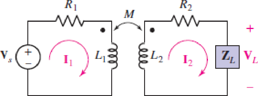
Assume the following values for the circuit depicted schematically in Fig. 13.16: R1 = R2 = 5 Ω, L1 = 2 μH, L2 = 1 μH, and M = 800 nH. Calculate the input impedance for ω = 107 rad/s if ZL is equal to (a) 1 Ω; (b) j Ω; (c) −j Ω; (d)  .
.
FIGURE 13.16 A linear transformer containing a source in the primary circuit and a load in the secondary circuit. Resistance is also included in both the primary and the secondary.
Expert Solution & Answer
Want to see the full answer?
Check out a sample textbook solution
Students have asked these similar questions
Q13) An ideal transformer connected to a 240V mains, supplies a 12V, 150W lamp. Calculate the Transformer turns ratio.
a.
45
b.
0.05
c.
50
d.
5
We want to build an impedance matching transformer that matches the output impedance of an amplifier connected to the primary, with a number of turns Np, whose impedance is 600 Ω, with an 8Ω speaker connected to the secondary, with a number of turns Ns. The Np/Ns transformation ratio of the matcher is:
answer:8,66
DESIGN A CONVENTIONAL POWER SUPPLY USING 220V AC , 10 KILO OHMS RESISTOR ,4 SILICON DIODES, CAPACITOR , TRANSFORMER WITH 20:1 TURNS' RATIO AND PERCENTAGE ERROR= 5 PERCENT.
FIND THE SUITABLE REGULATOR
Chapter 13 Solutions
Loose Leaf for Engineering Circuit Analysis Format: Loose-leaf
Ch. 13.1 - Assuming M = 10 H, coil L2 is open-circuited, and...Ch. 13.1 - For the circuit of Fig. 13.9, write appropriate...Ch. 13.1 - For the circuit of Fig. 13.11, write an...Ch. 13.2 - Let is = 2 cos 10t A in the circuit of Fig. 13.14,...Ch. 13.3 - Element values for a certain linear transformer...Ch. 13.3 - (a) If the two networks shown in Fig. 13.20 are...Ch. 13.3 - If the networks in Fig. 13.23 are equivalent,...Ch. 13.4 - Prob. 8PCh. 13.4 - Let N1 = 1000 turns and N2 = 5000 turns in the...Ch. 13 - Prob. 1E
Ch. 13 - With respect to Fig. 13.36, assume L1 = 500 mH, L2...Ch. 13 - The circuit in Fig. 13.36 has a sinusoidal input...Ch. 13 - Prob. 4ECh. 13 - Prob. 5ECh. 13 - The circuit in Fig. 13.38 has a sinusoidal input...Ch. 13 - The physical construction of three pairs of...Ch. 13 - Prob. 8ECh. 13 - Prob. 9ECh. 13 - Calculate v1 and v2 if i1 = 5 sin 40t mA and i2 =...Ch. 13 - Prob. 11ECh. 13 - For the circuit of Fig. 13.41, calculate I1, I2,...Ch. 13 - Prob. 13ECh. 13 - Prob. 14ECh. 13 - In the circuit of Fig. 13.43, M is reduced by an...Ch. 13 - Prob. 16ECh. 13 - Prob. 17ECh. 13 - Prob. 18ECh. 13 - Prob. 19ECh. 13 - Note that there is no mutual coupling between the...Ch. 13 - Prob. 21ECh. 13 - (a) Find Zin(j) for the network of Fig 13.50. (b)...Ch. 13 - For the coupled coils of Fig. 13.51, L1 = L2 = 10...Ch. 13 - Prob. 24ECh. 13 - Prob. 25ECh. 13 - Prob. 26ECh. 13 - Consider the circuit represented in Fig. 13.53....Ch. 13 - Compute v1, v2, and the average power delivered to...Ch. 13 - Assume the following values for the circuit...Ch. 13 - Prob. 30ECh. 13 - Prob. 31ECh. 13 - Prob. 32ECh. 13 - Prob. 33ECh. 13 - Prob. 34ECh. 13 - Prob. 35ECh. 13 - Prob. 36ECh. 13 - Prob. 37ECh. 13 - FIGURE 13.60 For the circuit of Fig. 13.60, redraw...Ch. 13 - Prob. 39ECh. 13 - Prob. 40ECh. 13 - Calculate the average power delivered to the 400 m...Ch. 13 - Prob. 42ECh. 13 - Calculate the average power delivered to each...Ch. 13 - Prob. 44ECh. 13 - Prob. 45ECh. 13 - Prob. 46ECh. 13 - Prob. 47ECh. 13 - Prob. 48ECh. 13 - A transformer whose nameplate reads 2300/230 V, 25...Ch. 13 - Prob. 52ECh. 13 - As the lead singer in the local rock band, you...Ch. 13 - Obtain an expression for V2/Vs in the circuit of...Ch. 13 - Prob. 55E
Knowledge Booster


Learn more about
Need a deep-dive on the concept behind this application? Look no further. Learn more about this topic, electrical-engineering and related others by exploring similar questions and additional content below.Similar questions
- An Electrical engineer is asked by a client to prepare a technical specification on specific items connected with a project. Hence, the engineer is requested to prepare the technical specification of the following: PROJECT: A Subdivision Development Lot AREA; 2 Hectares LOCATION: Brgy. Kanlurang Mayao, Lucna City Technical specification of fuse cutout Technical specification of transformerarrow_forwardsingle coil 600 turns instrument transformer, operating in the step-down mode with a 40 percent tap, supplies a 5 kVA, 0.88 power factor inductive load. The input to the transformer is 3.3 kV, 50 Hz. Assume that leakage effects and minor losses in transformer are negligible. Determine the following : (0) Turn ratio; (ii) Load current(in Amp); (iii) Incoming line current(in Amp); (iv) Transformed current (in Amp); (v) Apparent power conducted(in kVA)and (vi) Apparent power transformed"arrow_forwardGiven a 115kV/13.2kV distribution transformer rated at 30MVA with an 8% nameplate impedance what is the full Load current in ampsarrow_forward
- "A single coil 800 turns instrument transformer, operating in the step-downs mode with a 25 percent tap, supplies a 10 kVA, 0.80 power factor lagging load. The input to the transformer is 6600 V, 50 Hz. Assume that leakage effects and minor losses in transformer are negligible. Determine the following : (i) Turn ratio; (ii) Load current(in Amp); (iii) Incoming line current(in Amp); (iv) Transformed current (in Amp); (v) Apparent power conducted(in kVA)and (vi) Apparent power transformed"arrow_forwardA 2.4-kVA, 2400/240-V, 50-Hz, step-down transformer has the followingparameters: R, = 1.5 a, X, = 2.5 R, R, = 0.02 a, X, = 0.03 Q, R,, = 6 kR,and X,, = 8 kR. It is operating at 80% of its load at unity power factor.Using the exact equivalent circuit embodying the ideal transformer, determine the efficiency of the transformer. Also sketch its phasor diagram.arrow_forwardFor the Circuit shown, Let: VCC = 3.3V R1 = 85 kΩ RE = 500 Ω R2 = 35 k Ω RC = 4k Ω β = 150 Using approximation, determine the Q-point parameters: IBQ, ICQ, and VCEQ. Indicate the exact numerical values, following the given unit.arrow_forward
- You are the engineer responsible for parameterizing the relay of a substation with a 500kVA transformer, transformation ratio of 13.8-0.38/0.22kV and impedance of 4.5%. The local network sent you a new equivalent impedance at the delivery point and the relay installed in the primary cabin activated function 50, disabling the medium voltage switch. Remembering that the primary cabin has a protective CT of 150:5A and TP with a transformation ratio of 13800/R3:115/R3 resulting in an RTP of 120:1. A) Calculate the symmetrical three-phase short circuit level in the primary cabinet to determine the current passing through the relay reading during a fault.arrow_forwardWhat is a Nominal diameter , Power rating, X Max,f/pl(mm),coil (mm),Nominal impedance (O),Sensitivity (dB), Voice coil diameter, Surround Material Cloth - Sealed, Magnet type Ceramic, Magnet assembly flux (T) , Magnet weight (oz), Chassis type Pressed Steel, Cone material Kevlar loaded paper?arrow_forwardYou are tasked to design a dc power supply that operates from a single-phase ac supply (50Hz) with source inductanceof 1.5mH/phase. It is required to supply a dc load (resistive) with 55A at 322 Volt. Assume infinite inductive filtering andthe use of power diodes with a forward voltdrop of 0.7V. Consider the bridge converter topology and specify the followingdesign parameters,30) the loss in voltage due to commutation overlap;31) the r.m.s. ac supply voltage required;32) the overlap angle;33) the transformer utilisation factor;34) the rectification efficiency of the converter;35) the dc current rating of the rectifier diodes;36) the r.m.s. current rating of the rectifier diodes;37) the form factor of the diode current;38) the peak repetitive forward current rating of the rectifier diodes;39) the peak repetitive reverse voltage rating of the rectifier diodes.arrow_forward
- Electrical engineering A 375 kVA, 6600/400 V, 3-phase core type transformer has a total loss of 3700 watts on full load. The transformer tank is 1.25 m in height and 1 m × 0.5 m in plan. Design a suitable scheme for cooling tubes if the average temperature rise is to be limited to 35 °C. The diameter of the tube is 50 mm and are spaced 75 mm from each other. The average height of the tube is 1.05 m.arrow_forward*Proper Engineering Prefixes, (for micro use "u", example: 12.345 uA)*Strictly Three Decimal Places ONLY (example: 12.500 V)*FOR RESISTOR VALUES, Use Capital Letter "O", example: "123.456 kO" IMPORTANT: Do not round-off values in between calculations. ONLY THE FINAL ANSWER is rounded-off. Answer the ff: 1. What is the value of the base current? 2. What is the dc potential difference between the collector and emitter terminals? 3. What is the value of the input impedance? 4. What is the value of the output impedance? 5. What is the value of the voltage gain?arrow_forward1) A 600 V source feeds a 480 V load with a transformer Conventional 5000 VA, 480/120 V. Consider the ideal transformer. a) Calculate the apparent nominal power of the transformer in the connection as Autotransformer. b) Calculate the currents on the high voltage side and on the low voltage side in these conditions. c) Calculate the current in the common coil in the connection as Autotransformer.arrow_forward
arrow_back_ios
SEE MORE QUESTIONS
arrow_forward_ios
Recommended textbooks for you
 Introductory Circuit Analysis (13th Edition)Electrical EngineeringISBN:9780133923605Author:Robert L. BoylestadPublisher:PEARSON
 Delmar's Standard Textbook Of ElectricityElectrical EngineeringISBN:9781337900348Author:Stephen L. HermanPublisher:Cengage Learning
 Programmable Logic ControllersElectrical EngineeringISBN:9780073373843Author:Frank D. PetruzellaPublisher:McGraw-Hill Education
 Fundamentals of Electric CircuitsElectrical EngineeringISBN:9780078028229Author:Charles K Alexander, Matthew SadikuPublisher:McGraw-Hill Education
 Electric Circuits. (11th Edition)Electrical EngineeringISBN:9780134746968Author:James W. Nilsson, Susan RiedelPublisher:PEARSON
 Engineering ElectromagneticsElectrical EngineeringISBN:9780078028151Author:Hayt, William H. (william Hart), Jr, BUCK, John A.Publisher:Mcgraw-hill Education,
Introductory Circuit Analysis (13th Edition)
Electrical Engineering
ISBN:9780133923605
Author:Robert L. Boylestad
Publisher:PEARSON
Delmar's Standard Textbook Of Electricity
Electrical Engineering
ISBN:9781337900348
Author:Stephen L. Herman
Publisher:Cengage Learning
Programmable Logic Controllers
Electrical Engineering
ISBN:9780073373843
Author:Frank D. Petruzella
Publisher:McGraw-Hill Education
Fundamentals of Electric Circuits
Electrical Engineering
ISBN:9780078028229
Author:Charles K Alexander, Matthew Sadiku
Publisher:McGraw-Hill Education
Electric Circuits. (11th Edition)
Electrical Engineering
ISBN:9780134746968
Author:James W. Nilsson, Susan Riedel
Publisher:PEARSON
Engineering Electromagnetics
Electrical Engineering
ISBN:9780078028151
Author:Hayt, William H. (william Hart), Jr, BUCK, John A.
Publisher:Mcgraw-hill Education,
Current Divider Rule; Author: Neso Academy;https://www.youtube.com/watch?v=hRU1mKWUehY;License: Standard YouTube License, CC-BY