
Statics and Mechanics of Materials Plus Mastering Engineering with Pearson eText - Access Card Package (5th Edition)
5th Edition
ISBN: 9780134301006
Author: Russell C. Hibbeler
Publisher: PEARSON
expand_more
expand_more
format_list_bulleted
Concept explainers
Videos
Textbook Question
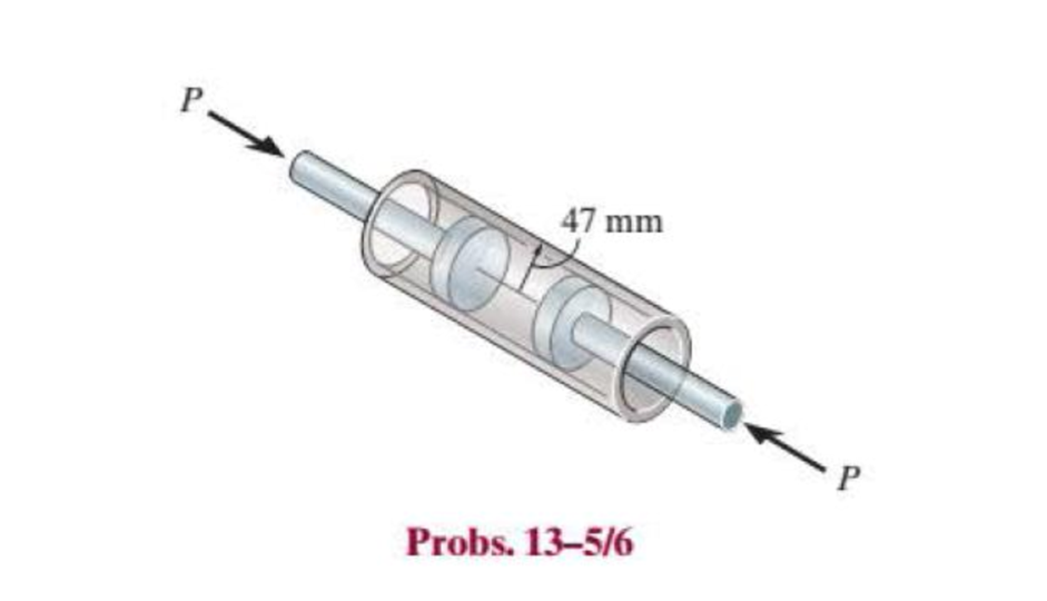
Chapter 13.1, Problem 6P
Determine the maximum force P that can be exerted on each of the two pistons so that the circumferential stress in the cylinder does not exceed 3 MPa. Each piston has a radius of 45 mm and the cylinder has a wall thickness of 2 mm.
Expert Solution & Answer
Want to see the full answer?
Check out a sample textbook solution
Students have asked these similar questions
Rod BD is made of steel (E = 29 × 106 psi) and is used to brace the axially compressed member ABC. The maximum force that can be developed in member BD is 0.02P. If the stress must not exceed 18 ksi and the maximum change in length of BD must not exceed 0.001 times the length of ABC, determine the smallest-diameter rod that can be used for member BD. Take P = 148 kips.The smallest-diameter rod that can be used for member BD is in.
The clamp presses the smooth surface at E when tightening the screw. If the tension in the
bolt is 40 kN, determine the principal stress at points A and B and show the results on the
elements located at each of these points. The cross-sectional area at A and B is shown in the
adjacent figure.
300 mm
50 mm
30 mm
100 mm
B
25 mm
A
100 mm
-50 mm
Determine the maximum normal stress (in MPa) developed in the bar when it is subjected to a tension of P = 12 kN.
Chapter 13 Solutions
Statics and Mechanics of Materials Plus Mastering Engineering with Pearson eText - Access Card Package (5th Edition)
Ch. 13.1 - A spherical gas tank has an inner radius of r =...Ch. 13.1 - A pressurized spherical tank is made of...Ch. 13.1 - The thin-walled cylinder can be supported in one...Ch. 13.1 - Prob. 4PCh. 13.1 - Prob. 5PCh. 13.1 - Determine the maximum force P that can be exerted...Ch. 13.1 - Prob. 7PCh. 13.1 - The steel water pipe has an inner diameter of 12...Ch. 13.1 - The steel water pipe has an inner diameter of 12...Ch. 13.1 - The A-36-steel band is 2 in. wide and is secured...
Ch. 13.1 - The gas pipe line is supported every 20 ft by...Ch. 13.1 - Prob. 12PCh. 13.1 - An A-36-steel hoop has an inner diameter of 23.99...Ch. 13.1 - The ring, having the dimensions shown, is placed...Ch. 13.1 - Prob. 15PCh. 13.1 - Prob. 16PCh. 13.1 - Prob. 17PCh. 13.2 - In each case, determine the internal loadings that...Ch. 13.2 - The internal loadings act on the section. Show the...Ch. 13.2 - Determine the normal stress at comers A and B of...Ch. 13.2 - Determine the state of stress at point A on the...Ch. 13.2 - Determine the state of stress at point A on the...Ch. 13.2 - Determine the magnitude of the load P that will...Ch. 13.2 - Prob. 5FPCh. 13.2 - Determine the state of stress at point A on the...Ch. 13.2 - Determine the state of stress at point A on the...Ch. 13.2 - Determine the state of stress at point A on the...Ch. 13.2 - Determine the shortest distance d to the edge of...Ch. 13.2 - Determine the maximum distance d to the edge of...Ch. 13.2 - The plate has a thickness of 20 mm and the force P...Ch. 13.2 - If the load has a weight of 600 lb, determine the...Ch. 13.2 - The steel bracket is used to connect the ends of...Ch. 13.2 - Prob. 23PCh. 13.2 - The column is built up by gluing the two boards...Ch. 13.2 - Prob. 25PCh. 13.2 - The screw of the clamp exerts a compressive force...Ch. 13.2 - Prob. 27PCh. 13.2 - Prob. 28PCh. 13.2 - The joint is subjected to the force system shown....Ch. 13.2 - Prob. 30PCh. 13.2 - The 12-in.-diameter holt hook is subjected to the...Ch. 13.2 - Prob. 32PCh. 13.2 - Prob. 33PCh. 13.2 - Prob. 34PCh. 13.2 - Prob. 35PCh. 13.2 - The drill is jammed in the wall and is subjected...Ch. 13.2 - The drill is jammed in the wall and is subjected...Ch. 13.2 - The frame supports the distributed load shown....Ch. 13.2 - Prob. 39PCh. 13.2 - The rod has a diameter of 40 mm. If it is...Ch. 13.2 - The rod has a diameter of 40 mm. If it is...Ch. 13.2 - The beveled gear is subjected to the loads shown....Ch. 13.2 - The beveled gear is subjected to the loads shown....Ch. 13.2 - Determine the normal-stress developed at points A...Ch. 13.2 - Sketch the normal-stress distribution acting over...Ch. 13.2 - Prob. 46PCh. 13.2 - The solid rod is subjected to the loading shown....Ch. 13.2 - Prob. 48PCh. 13.2 - Prob. 49PCh. 13.2 - The C-frame is used in a riveting machine. If the...Ch. 13.2 - Prob. 51PCh. 13.2 - The uniform sign has a weight of 1500 lb and is...Ch. 13.2 - The uniform sign has a weight of 1500 lb and is...Ch. 13 - The post has a circular cross section of radius c....Ch. 13 - The 20-kg drum is suspended from the hook mounted...Ch. 13 - The 20-kg drum is suspended from the hook mounted...Ch. 13 - Prob. 4RPCh. 13 - If the cross section of the femur at section aa...Ch. 13 - Prob. 6RPCh. 13 - Prob. 7RPCh. 13 - Prob. 8RP
Knowledge Booster


Learn more about
Need a deep-dive on the concept behind this application? Look no further. Learn more about this topic, mechanical-engineering and related others by exploring similar questions and additional content below.Similar questions
- Determine the maximum compressive force that can be applied on a circular member of diameter 40 mm. The compressive strength of the member is 90 kPa.arrow_forwardplease answer it correctlyarrow_forwardDetermine the maximum distance d to the edge of the plate at which the force P can be applied so that it produces no compressive stresses on the plate at section a–a. The plate has a thickness of 20 mm and P acts along thecenterline of this thickness.arrow_forward
- The yoke-and-rod connection is subjected to a tensile force P. The end of the 40-mm diameter rod is embedded inside a wall at a length I of 100 mm using epoxy adhesive. If the allowable normal stress for the rods is 60 MPa, the allowable shear stress for the 25- mm diameter pin A is 50 MPa, and the allowable shear stress of the epoxy adhesive is 6 MPa, determine the largest force P that can be applied to the assembly. Note: Show your calculations for all types of stresses in detail. 40 mm 30 mm A 25 mm P.arrow_forwardThe solid bar has a diameter of 50 mm. The two forces and the torque Tx are acting at the origin of the x-y-z coordinate system which is coincident with the centroid of the cross-section of the bar; the 1800 N force is acting in the y-z plane and torque T is acting about the x-axis. Determine the state of stress at points A and B, and show the respective stress components acting on differential elements located at these two points. {30 marks} 200 mm y 200 mm B. 1200 N T= 40 N.m 1800 Narrow_forwardThe 10-mm-diameter steel bolt is surrounded by a bronze sleeve. The outer diameter of this sleeve is 20 mm, and its inner diameter is 10 mm. If the bolt is subjected to a compressive force of P = 20 kN, determine the average normal stress in the steel and the bronze. Est = 200 GPa, Ebr = 100 GPa.arrow_forward
- If the allowable tensile stress for wires AB and AC is sallow = 180 MPa, and wire AB has a diameter of 5 mm and AC has a diameter of 6 mm, determine the greatest force P that can be applied to the chain.arrow_forwardThe two rods support the vertical force of P = 40 kN. Determine the normal stress in rod AB and AC if they each have a diameter of 20 mm. Answers: (a) 180 MPa, 127 MPa (b) 152 MPa, 114 MPa (c) 127 MPa, 152 MPa (d) 114 MPa, 180 MPa A P 45° Barrow_forwardDetermine the magnitude of the pin force at B. at 0.61 m 0.39 m 0.39 m 280 N-m 0.39 m B Answer: B = i Narrow_forward
- The bar of negligible weight is supported by two springs,each having a stiffness k = 80 N>m. If the springs are originally unstretched, and the force is vertical as shown,determine the angle theta the bar makes with the horizontal,when the 45-N force is applied to the bar. 1.5 m- 3 m C В 45 Narrow_forwardThe solid bar has a diameter of 50 mm. The two forces and the torque Tx are acting at the origin of the x-y-z coordinate system which is coincident with the centroid of the cross-section of the bar; the 1800 N force is acting in the y-z plane and torque Tx is acting about the x-axis. Determine the state of stress at points A and B, and show the respective stress components acting on differential elements located at these two points. 200 mm/ y 200 mm 1200 N Tx = 40 N.m %3D 1800 Narrow_forwardThe d = 13-mm-diameter solid rod passes through a D=21-mm-diameter hole in the support plate. When a load P is applied to the rod, the rod head rests on the support plate. The support plate has a thickness of b = 12 mm. The rod head has a diameter of a = 28 mm, and the head has a thickness of t = 8 mm. If the normal stress produced in the rod by load P is 150 MPa, determine (a) the bearing stress acting between the support plate and the rod head. (b) the average shear stress produced in the rod head. (c) the punching shear stress produced in the support plate by the rod head. Support Plate Hole diameter D Rod Head b Calculate the cross-sectional area of the rod. Answer: Arod mm²arrow_forward
arrow_back_ios
SEE MORE QUESTIONS
arrow_forward_ios
Recommended textbooks for you
 Elements Of ElectromagneticsMechanical EngineeringISBN:9780190698614Author:Sadiku, Matthew N. O.Publisher:Oxford University Press
 Mechanics of Materials (10th Edition)Mechanical EngineeringISBN:9780134319650Author:Russell C. HibbelerPublisher:PEARSON
 Thermodynamics: An Engineering ApproachMechanical EngineeringISBN:9781259822674Author:Yunus A. Cengel Dr., Michael A. BolesPublisher:McGraw-Hill Education
 Control Systems EngineeringMechanical EngineeringISBN:9781118170519Author:Norman S. NisePublisher:WILEY
 Mechanics of Materials (MindTap Course List)Mechanical EngineeringISBN:9781337093347Author:Barry J. Goodno, James M. GerePublisher:Cengage Learning
 Engineering Mechanics: StaticsMechanical EngineeringISBN:9781118807330Author:James L. Meriam, L. G. Kraige, J. N. BoltonPublisher:WILEY
Elements Of Electromagnetics
Mechanical Engineering
ISBN:9780190698614
Author:Sadiku, Matthew N. O.
Publisher:Oxford University Press
Mechanics of Materials (10th Edition)
Mechanical Engineering
ISBN:9780134319650
Author:Russell C. Hibbeler
Publisher:PEARSON
Thermodynamics: An Engineering Approach
Mechanical Engineering
ISBN:9781259822674
Author:Yunus A. Cengel Dr., Michael A. Boles
Publisher:McGraw-Hill Education
Control Systems Engineering
Mechanical Engineering
ISBN:9781118170519
Author:Norman S. Nise
Publisher:WILEY
Mechanics of Materials (MindTap Course List)
Mechanical Engineering
ISBN:9781337093347
Author:Barry J. Goodno, James M. Gere
Publisher:Cengage Learning
Engineering Mechanics: Statics
Mechanical Engineering
ISBN:9781118807330
Author:James L. Meriam, L. G. Kraige, J. N. Bolton
Publisher:WILEY
Pressure Vessels Introduction; Author: Engineering and Design Solutions;https://www.youtube.com/watch?v=Z1J97IpFc2k;License: Standard youtube license