
Statics and Mechanics of Materials Plus Mastering Engineering with Pearson eText - Access Card Package (5th Edition)
5th Edition
ISBN: 9780134301006
Author: Russell C. Hibbeler
Publisher: PEARSON
expand_more
expand_more
format_list_bulleted
Videos
Textbook Question
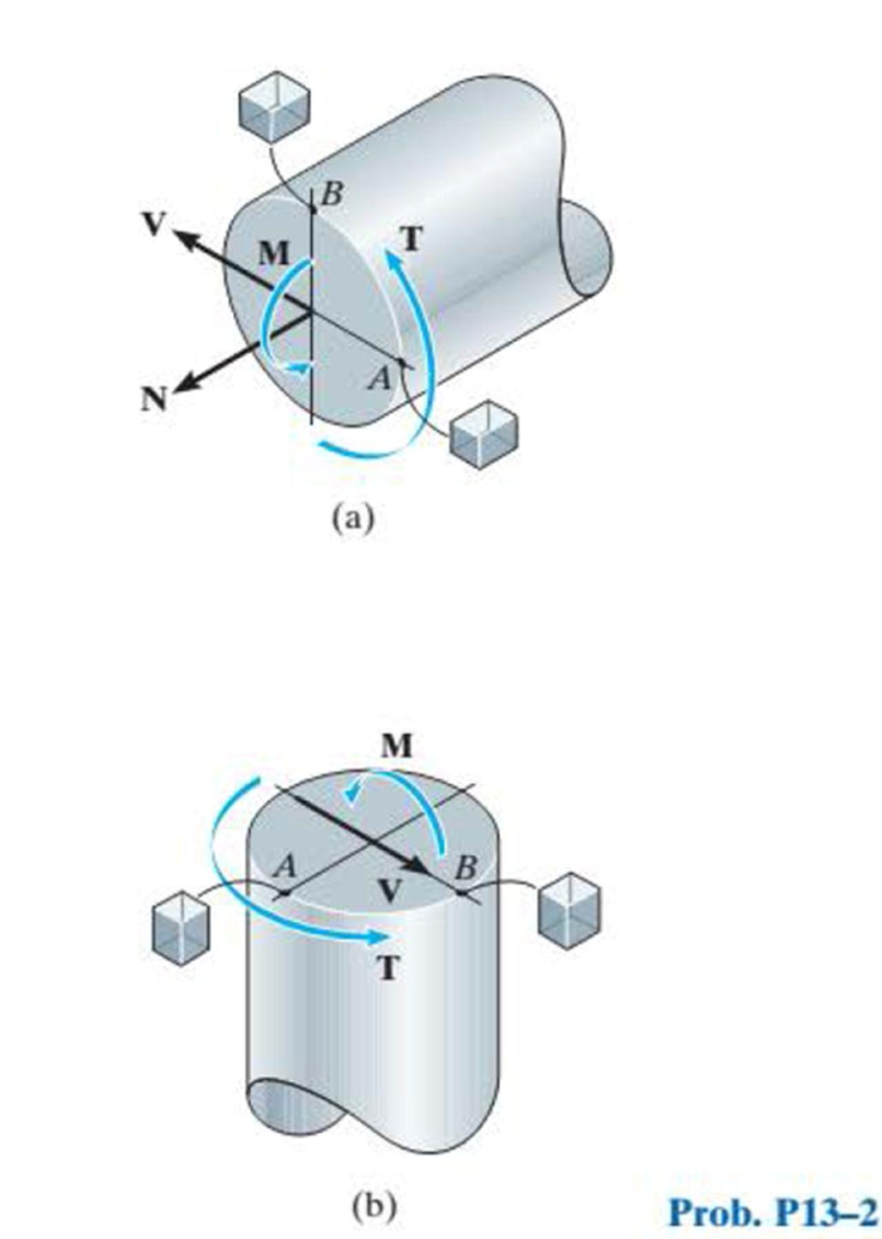
Chapter 13.2, Problem 2PP
The internal loadings act on the section. Show the stress that each of these loads produce on differential elements located at point A and point B.
Expert Solution & Answer
Want to see the full answer?
Check out a sample textbook solution
Students have asked these similar questions
The solid circular rod has a cross-sectional area of 360 mm². It is subjected to a uniform axial distributed loading along its length of w=
8 kN/m. Two concentrated loads also act on the rod: P = 7 kN and Q = 3 kN. Determine the normal stress in the rod at x = 0.1 m. Assume
a=0.4 m and b = 1.3 m.
a
B
b
The solid bar has a diameter of 50 mm. The two forces and the torque Tx are acting at the origin of
the x-y-z coordinate system which is coincident with the centroid of the cross-section of the bar;
the 1800 N force is acting in the y-z plane and torque T is acting about the x-axis. Determine the
state of stress at points A and B, and show the respective stress components acting on differential
elements located at these two points. {30 marks}
200 mm
y 200 mm
B.
1200 N
T= 40 N.m
1800 N
The solid bar has a diameter of 50 mm. The two forces and the torque Tx are acting at the origin of
the x-y-z coordinate system which is coincident with the centroid of the cross-section of the bar;
the 1800 N force is acting in the y-z plane and torque Tx is acting about the x-axis. Determine the
state of stress at points A and B, and show the respective stress components acting on differential
elements located at these two points.
200 mm/
y 200 mm
1200 N
Tx = 40 N.m
%3D
1800 N
Chapter 13 Solutions
Statics and Mechanics of Materials Plus Mastering Engineering with Pearson eText - Access Card Package (5th Edition)
Ch. 13.1 - A spherical gas tank has an inner radius of r =...Ch. 13.1 - A pressurized spherical tank is made of...Ch. 13.1 - The thin-walled cylinder can be supported in one...Ch. 13.1 - Prob. 4PCh. 13.1 - Prob. 5PCh. 13.1 - Determine the maximum force P that can be exerted...Ch. 13.1 - Prob. 7PCh. 13.1 - The steel water pipe has an inner diameter of 12...Ch. 13.1 - The steel water pipe has an inner diameter of 12...Ch. 13.1 - The A-36-steel band is 2 in. wide and is secured...
Ch. 13.1 - The gas pipe line is supported every 20 ft by...Ch. 13.1 - Prob. 12PCh. 13.1 - An A-36-steel hoop has an inner diameter of 23.99...Ch. 13.1 - The ring, having the dimensions shown, is placed...Ch. 13.1 - Prob. 15PCh. 13.1 - Prob. 16PCh. 13.1 - Prob. 17PCh. 13.2 - In each case, determine the internal loadings that...Ch. 13.2 - The internal loadings act on the section. Show the...Ch. 13.2 - Determine the normal stress at comers A and B of...Ch. 13.2 - Determine the state of stress at point A on the...Ch. 13.2 - Determine the state of stress at point A on the...Ch. 13.2 - Determine the magnitude of the load P that will...Ch. 13.2 - Prob. 5FPCh. 13.2 - Determine the state of stress at point A on the...Ch. 13.2 - Determine the state of stress at point A on the...Ch. 13.2 - Determine the state of stress at point A on the...Ch. 13.2 - Determine the shortest distance d to the edge of...Ch. 13.2 - Determine the maximum distance d to the edge of...Ch. 13.2 - The plate has a thickness of 20 mm and the force P...Ch. 13.2 - If the load has a weight of 600 lb, determine the...Ch. 13.2 - The steel bracket is used to connect the ends of...Ch. 13.2 - Prob. 23PCh. 13.2 - The column is built up by gluing the two boards...Ch. 13.2 - Prob. 25PCh. 13.2 - The screw of the clamp exerts a compressive force...Ch. 13.2 - Prob. 27PCh. 13.2 - Prob. 28PCh. 13.2 - The joint is subjected to the force system shown....Ch. 13.2 - Prob. 30PCh. 13.2 - The 12-in.-diameter holt hook is subjected to the...Ch. 13.2 - Prob. 32PCh. 13.2 - Prob. 33PCh. 13.2 - Prob. 34PCh. 13.2 - Prob. 35PCh. 13.2 - The drill is jammed in the wall and is subjected...Ch. 13.2 - The drill is jammed in the wall and is subjected...Ch. 13.2 - The frame supports the distributed load shown....Ch. 13.2 - Prob. 39PCh. 13.2 - The rod has a diameter of 40 mm. If it is...Ch. 13.2 - The rod has a diameter of 40 mm. If it is...Ch. 13.2 - The beveled gear is subjected to the loads shown....Ch. 13.2 - The beveled gear is subjected to the loads shown....Ch. 13.2 - Determine the normal-stress developed at points A...Ch. 13.2 - Sketch the normal-stress distribution acting over...Ch. 13.2 - Prob. 46PCh. 13.2 - The solid rod is subjected to the loading shown....Ch. 13.2 - Prob. 48PCh. 13.2 - Prob. 49PCh. 13.2 - The C-frame is used in a riveting machine. If the...Ch. 13.2 - Prob. 51PCh. 13.2 - The uniform sign has a weight of 1500 lb and is...Ch. 13.2 - The uniform sign has a weight of 1500 lb and is...Ch. 13 - The post has a circular cross section of radius c....Ch. 13 - The 20-kg drum is suspended from the hook mounted...Ch. 13 - The 20-kg drum is suspended from the hook mounted...Ch. 13 - Prob. 4RPCh. 13 - If the cross section of the femur at section aa...Ch. 13 - Prob. 6RPCh. 13 - Prob. 7RPCh. 13 - Prob. 8RP
Knowledge Booster


Learn more about
Need a deep-dive on the concept behind this application? Look no further. Learn more about this topic, mechanical-engineering and related others by exploring similar questions and additional content below.Similar questions
- The solid circular rod has a cross-sectional area of 360 mm². It is subjected to a uniform axial distributed loading along its length of w= 8 kN/m. Two concentrated loads also act on the rod: P = 5 kN and Q = 2 kN. Determine the normal stress in the rod at x = 0.4 m. Assume a=0.7 m and b=0.9 m. barrow_forwardAt point A & C, the beam is pin connected. Therefore, find the average normal stress in the 20-mm-diameter cable AB and CD and the average shear stress in the 15-mm-diameter pin at B and D.arrow_forwardThe tube has an inner diameter d; = 20 mm and an outer diameter d, = 22 mm. It is subjected to an internal pressure of 1 MPa and the loads shown below. Determine the stress at point A and draw it on a stress element. 200 mm 400 mm 150 N-m 600 N 1500 N 800 Narrow_forward
- The steel rod has a circular cross section. If it is loaded by a 500 lb vertical force as shown, determine the normal stress at point A and B on the cross section. Oat A = Oat B = в A 0.6 in | 500 lb 4 in 1.5 in B 2.7 inarrow_forwardThe frame supports the distributed load shown. Determine the state of stress acting at point D. Show the results on a differential element at this point.arrow_forwardDetermine the maximum distance d to the edge of the plate at which the force P can be applied so that it produces no compressive stresses on the plate at section a–a. The plate has a thickness of 20 mm and P acts along thecenterline of this thickness.arrow_forward
- The plate has a thickness of 20 mm and the force P = 3 kN acts along the centerline of this thickness such that d = 150 mm. Plot the distribution of normal stress acting along section a–a.arrow_forwardThe solid cylinder having a radius r is placed in a sealed container and subjected to a pressure p. Determine the stress components acting at point A located on the center line of the cylinder. Draw Mohr's circles for the element at this point. Aarrow_forwardThe solid circular rod has a cross-sectional area of 450 mm². It is subjected to a uniform axial distributed loading along its length of w= 7 kN/m. Two concentrated loads also act on the rod: P = 4 kN and Q = 6 kN. Determine the normal stress in the rod at x = 1.3 m. Assume a = 0.5 m and b = 1.0 m. W B x a P barrow_forward
- The screw of the clamp exerts a compressive force of 500 lb on the wood blocks. Determine the maximum normal stress along section a–a. The cross section is rectangular, 0.75 in. by 0.50 in.arrow_forwardThe element that has a rectangular cross section, it is designed to resist a moment of 40 N-m. To increase its resistance and rigidity, it is proposed to add two small ribs to its lower part. Determine the maximum normal stress in the member for both cases.arrow_forwardDo it clearlyarrow_forward
arrow_back_ios
SEE MORE QUESTIONS
arrow_forward_ios
Recommended textbooks for you
 Elements Of ElectromagneticsMechanical EngineeringISBN:9780190698614Author:Sadiku, Matthew N. O.Publisher:Oxford University Press
 Mechanics of Materials (10th Edition)Mechanical EngineeringISBN:9780134319650Author:Russell C. HibbelerPublisher:PEARSON
 Thermodynamics: An Engineering ApproachMechanical EngineeringISBN:9781259822674Author:Yunus A. Cengel Dr., Michael A. BolesPublisher:McGraw-Hill Education
 Control Systems EngineeringMechanical EngineeringISBN:9781118170519Author:Norman S. NisePublisher:WILEY
 Mechanics of Materials (MindTap Course List)Mechanical EngineeringISBN:9781337093347Author:Barry J. Goodno, James M. GerePublisher:Cengage Learning
 Engineering Mechanics: StaticsMechanical EngineeringISBN:9781118807330Author:James L. Meriam, L. G. Kraige, J. N. BoltonPublisher:WILEY
Elements Of Electromagnetics
Mechanical Engineering
ISBN:9780190698614
Author:Sadiku, Matthew N. O.
Publisher:Oxford University Press
Mechanics of Materials (10th Edition)
Mechanical Engineering
ISBN:9780134319650
Author:Russell C. Hibbeler
Publisher:PEARSON
Thermodynamics: An Engineering Approach
Mechanical Engineering
ISBN:9781259822674
Author:Yunus A. Cengel Dr., Michael A. Boles
Publisher:McGraw-Hill Education
Control Systems Engineering
Mechanical Engineering
ISBN:9781118170519
Author:Norman S. Nise
Publisher:WILEY
Mechanics of Materials (MindTap Course List)
Mechanical Engineering
ISBN:9781337093347
Author:Barry J. Goodno, James M. Gere
Publisher:Cengage Learning
Engineering Mechanics: Statics
Mechanical Engineering
ISBN:9781118807330
Author:James L. Meriam, L. G. Kraige, J. N. Bolton
Publisher:WILEY
An Introduction to Stress and Strain; Author: The Efficient Engineer;https://www.youtube.com/watch?v=aQf6Q8t1FQE;License: Standard YouTube License, CC-BY