
Statics and Mechanics of Materials Plus Mastering Engineering with Pearson eText - Access Card Package (5th Edition)
5th Edition
ISBN: 9780134301006
Author: Russell C. Hibbeler
Publisher: PEARSON
expand_more
expand_more
format_list_bulleted
Concept explainers
Videos
Textbook Question
Chapter 13.2, Problem 36P
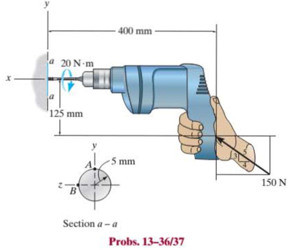
The drill is jammed in the wall and is subjected to the torque and force shown. Determine the state of stress at point A on the cross section of the drill bit at section a–a.
Expert Solution & Answer
Want to see the full answer?
Check out a sample textbook solution
Students have asked these similar questions
Determine the maximum ram force P that can be applied to the clamp at D if the allowable normal stress for the material is sallow = 180 MPa.
The supporting wheel on a scaffold is held in place on the leg using a 4- mm -diameter pin as shown. If the wheel is subjected to a normal force of P = 2.3 kN , determine the average shear stress developed in the pin. Neglect friction between the inner scaffold puller leg and the tube used on the wheel.
The bearings at A and B exert only x and z components of force on the steel shaft. Determine the shaft’s diameter to the nearest millimeter so that it can resist the loadings of the gears without exceeding an allowable shear stress of 82 MPa. Use the maximum-shear-stress theory of failure.
Chapter 13 Solutions
Statics and Mechanics of Materials Plus Mastering Engineering with Pearson eText - Access Card Package (5th Edition)
Ch. 13.1 - A spherical gas tank has an inner radius of r =...Ch. 13.1 - A pressurized spherical tank is made of...Ch. 13.1 - The thin-walled cylinder can be supported in one...Ch. 13.1 - Prob. 4PCh. 13.1 - Prob. 5PCh. 13.1 - Determine the maximum force P that can be exerted...Ch. 13.1 - Prob. 7PCh. 13.1 - The steel water pipe has an inner diameter of 12...Ch. 13.1 - The steel water pipe has an inner diameter of 12...Ch. 13.1 - The A-36-steel band is 2 in. wide and is secured...
Ch. 13.1 - The gas pipe line is supported every 20 ft by...Ch. 13.1 - Prob. 12PCh. 13.1 - An A-36-steel hoop has an inner diameter of 23.99...Ch. 13.1 - The ring, having the dimensions shown, is placed...Ch. 13.1 - Prob. 15PCh. 13.1 - Prob. 16PCh. 13.1 - Prob. 17PCh. 13.2 - In each case, determine the internal loadings that...Ch. 13.2 - The internal loadings act on the section. Show the...Ch. 13.2 - Determine the normal stress at comers A and B of...Ch. 13.2 - Determine the state of stress at point A on the...Ch. 13.2 - Determine the state of stress at point A on the...Ch. 13.2 - Determine the magnitude of the load P that will...Ch. 13.2 - Prob. 5FPCh. 13.2 - Determine the state of stress at point A on the...Ch. 13.2 - Determine the state of stress at point A on the...Ch. 13.2 - Determine the state of stress at point A on the...Ch. 13.2 - Determine the shortest distance d to the edge of...Ch. 13.2 - Determine the maximum distance d to the edge of...Ch. 13.2 - The plate has a thickness of 20 mm and the force P...Ch. 13.2 - If the load has a weight of 600 lb, determine the...Ch. 13.2 - The steel bracket is used to connect the ends of...Ch. 13.2 - Prob. 23PCh. 13.2 - The column is built up by gluing the two boards...Ch. 13.2 - Prob. 25PCh. 13.2 - The screw of the clamp exerts a compressive force...Ch. 13.2 - Prob. 27PCh. 13.2 - Prob. 28PCh. 13.2 - The joint is subjected to the force system shown....Ch. 13.2 - Prob. 30PCh. 13.2 - The 12-in.-diameter holt hook is subjected to the...Ch. 13.2 - Prob. 32PCh. 13.2 - Prob. 33PCh. 13.2 - Prob. 34PCh. 13.2 - Prob. 35PCh. 13.2 - The drill is jammed in the wall and is subjected...Ch. 13.2 - The drill is jammed in the wall and is subjected...Ch. 13.2 - The frame supports the distributed load shown....Ch. 13.2 - Prob. 39PCh. 13.2 - The rod has a diameter of 40 mm. If it is...Ch. 13.2 - The rod has a diameter of 40 mm. If it is...Ch. 13.2 - The beveled gear is subjected to the loads shown....Ch. 13.2 - The beveled gear is subjected to the loads shown....Ch. 13.2 - Determine the normal-stress developed at points A...Ch. 13.2 - Sketch the normal-stress distribution acting over...Ch. 13.2 - Prob. 46PCh. 13.2 - The solid rod is subjected to the loading shown....Ch. 13.2 - Prob. 48PCh. 13.2 - Prob. 49PCh. 13.2 - The C-frame is used in a riveting machine. If the...Ch. 13.2 - Prob. 51PCh. 13.2 - The uniform sign has a weight of 1500 lb and is...Ch. 13.2 - The uniform sign has a weight of 1500 lb and is...Ch. 13 - The post has a circular cross section of radius c....Ch. 13 - The 20-kg drum is suspended from the hook mounted...Ch. 13 - The 20-kg drum is suspended from the hook mounted...Ch. 13 - Prob. 4RPCh. 13 - If the cross section of the femur at section aa...Ch. 13 - Prob. 6RPCh. 13 - Prob. 7RPCh. 13 - Prob. 8RP
Knowledge Booster


Learn more about
Need a deep-dive on the concept behind this application? Look no further. Learn more about this topic, mechanical-engineering and related others by exploring similar questions and additional content below.Similar questions
- The beveled gear is subjected to the loads shown.Determine the stress components acting on the shaftat point B, and draw the results on a stress elementat this point. The shaft has a diameter of 1 in. and isfixed to the wall at C. A = 0.7854 in2 J = 0.098175 in4 I = 0.049087 in4 (QB)z = 0 (QB)x = 0.0833 in3arrow_forwardThe short concrete cylinder having a diameter of 50 mm is subjected to a torque of 500 N # m and an axial compressive force of 2 kN. Determine if it fails according to the maximum normal stress theory. The ultimate stress of the concrete is sult = 28 MPa.arrow_forwardThe tubular shaft of the soil auger is subjected to the axial force and torque shown. If the auger is rotating at a constant rate, determine the state of stress at points A and B on the cross section of the shaft at section a-a. 1200 lb 3000 lb-ft 1 in. Az 1.5 in. B Section a-aarrow_forward
- The wheel on a trolley is held in place on the leg using a 5-mm-radius pin. If the wheel is subjected to a normal force of 10 kN, determine the average shear stress in the pin. Neglect the friction force and assume the pin only supports the vertical 10-kN loadarrow_forwardThe state of stress at a point in a member is shown on the element. Determine the stress components acting on the inclined plane AB. a. Solve the problem using the method of equilibrium b. Solve the problem using the stress-transformation equations developed. Show the result on a sketch. 2 ksi 3 ksi 4 ksi Barrow_forwardDetermine the maximum distance d to the edge of the plate at which the force P can be applied so that it produces no compressive stresses on the plate at section a–a. The plate has a thickness of 20 mm and P acts along thecenterline of this thickness.arrow_forward
- short link BC. If it is subjected to the force of 80 N, determine crank is constructed from an aluminum plate having a 9-29. The bell crank is pinned at A and supported by a supported by a 9-29. The bell crank is pinned at A and the principal stresses at (a) point D and (b) point E T 19 mm. thickness of5 80 N 50 mm -150 mm D 3 10 mm 40 mm- 50 mm 50 mm E 60 mm 15 mm Barrow_forwardI need the answer as soon as possiblearrow_forwardFast plzzarrow_forward
- Please solve by handarrow_forwardThe supporting wheel on a scaffold is held in place on the leg using a 4-mm-diameter pin. If the wheel is subjected to a normal force of 3 kN, determine the average shear stress in the pin. Assume the pin only supports the vertical 3-kN load.arrow_forwardThe solid bar has a diameter of 50 mm. The two forces and the torque Tx are acting at the origin of the x-y-z coordinate system which is coincident with the centroid of the cross-section of the bar; the 1800 N force is acting in the y-z plane and torque T is acting about the x-axis. Determine the state of stress at points A and B, and show the respective stress components acting on differential elements located at these two points. {30 marks} 200 mm y 200 mm B. 1200 N T= 40 N.m 1800 Narrow_forward
arrow_back_ios
SEE MORE QUESTIONS
arrow_forward_ios
Recommended textbooks for you
 Elements Of ElectromagneticsMechanical EngineeringISBN:9780190698614Author:Sadiku, Matthew N. O.Publisher:Oxford University Press
 Mechanics of Materials (10th Edition)Mechanical EngineeringISBN:9780134319650Author:Russell C. HibbelerPublisher:PEARSON
 Thermodynamics: An Engineering ApproachMechanical EngineeringISBN:9781259822674Author:Yunus A. Cengel Dr., Michael A. BolesPublisher:McGraw-Hill Education
 Control Systems EngineeringMechanical EngineeringISBN:9781118170519Author:Norman S. NisePublisher:WILEY
 Mechanics of Materials (MindTap Course List)Mechanical EngineeringISBN:9781337093347Author:Barry J. Goodno, James M. GerePublisher:Cengage Learning
 Engineering Mechanics: StaticsMechanical EngineeringISBN:9781118807330Author:James L. Meriam, L. G. Kraige, J. N. BoltonPublisher:WILEY
Elements Of Electromagnetics
Mechanical Engineering
ISBN:9780190698614
Author:Sadiku, Matthew N. O.
Publisher:Oxford University Press
Mechanics of Materials (10th Edition)
Mechanical Engineering
ISBN:9780134319650
Author:Russell C. Hibbeler
Publisher:PEARSON
Thermodynamics: An Engineering Approach
Mechanical Engineering
ISBN:9781259822674
Author:Yunus A. Cengel Dr., Michael A. Boles
Publisher:McGraw-Hill Education
Control Systems Engineering
Mechanical Engineering
ISBN:9781118170519
Author:Norman S. Nise
Publisher:WILEY
Mechanics of Materials (MindTap Course List)
Mechanical Engineering
ISBN:9781337093347
Author:Barry J. Goodno, James M. Gere
Publisher:Cengage Learning
Engineering Mechanics: Statics
Mechanical Engineering
ISBN:9781118807330
Author:James L. Meriam, L. G. Kraige, J. N. Bolton
Publisher:WILEY
Everything About COMBINED LOADING in 10 Minutes! Mechanics of Materials; Author: Less Boring Lectures;https://www.youtube.com/watch?v=N-PlI900hSg;License: Standard youtube license