
Videos
The summing amplifier in Figure P14.15 has an op−amp with open−loop parameters:
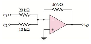
Figure P14.15
Want to see the full answer?
Check out a sample textbook solution
Chapter 14 Solutions
MICROELECT. CIRCUIT ANALYSIS&DESIGN (LL)


- Q2:-Find the output voltage Vo . Ry B2HF 100 kQ + 100 mV rms,arrow_forwardA step down converter has a load resistance R-0.5Ohms, an input voltage Vs-200V and a battery voltage E-OV. The average load current la-250A and the converter frequency is 1000 Hz. The value of the inductance L that would limit the maximum load ripple current to 5% of la, would be equal to: Select one: O a. 15 mH O b. None of these O c. 4 mH O d. 9 mHarrow_forwardQuestion 4. Design a C converter by drawing according to the values given below.The C ´uk converter has 24 V input and 36 V output providing 80 W load. In this case, choose Duty ratio, switching frequency, inductor dimensions so that the variation in inductor currents is not more than 5 percent of the average inductor current, output voltage fluctuation is less than 1 percent and voltage fluctuation at C1 is less than 5 percent.arrow_forward
- Boost Converter Design A boost converter is required to have an output voltage of 8 V and supply a load current of 1 A. The input voltage varies from 2.7 to 4.2 V. A control circuit adjusts the duty ratio to keep the output voltage constant. Select the switching frequency. Determine a value for the inductor such that the variation in inductor current is no more than 40 percent of the average inductor current for all operating conditions. Determine a value of an ideal capacitor such that the output voltage ripple is no more than 2 percent. Determine the maximum capacitor equivalent series resistance for a 2 percent ripple.arrow_forwardA boost converter is required to have an output voltage of 8 V and supply a load current of 1 A. The input voltage varies from 2.7 to 4.2 V. A control circuit adjusts the duty ratio to keep the output voltage constant. Select the switching frequency. Determine a value for the inductor such that the variation in inductor current is no more than 40 percent of the average inductor current for all operating conditions. Determine a value of an ideal capacitor such that the output voltage ripple is no more than 2 percent. Determine the maximum capacitor equivalent series resistance for a 2 percent ripple.arrow_forward45) We have buck converter, the maximum current of the inductor is Imax, the minimum inductor currentIs Imin. We now know the period of the switching signal is T=20 µs, the duty cycle D is 0.5, the load resistance R is 2 ohms, the input voltage is 30V, and the inductance L is 100 µH; What is Imax andIs Imin?arrow_forward
- For the following zener clipper draw the output waveform Vz1 = 5V, Vz1 = 7V VK = 0.8v lkn ISV V₁₂ 5V 2, 72. -5V Q2 Determine The Output Waveform And Calculate The current and PIV 1kQ 1kQ 10 V 10 si www www Q. For the circuit shown in Figure below (1),find the maximum and minimum values of zener diod current. Live 5 ΚΩ www I IL 15 80-120 V 10 ΚΩ LIR 101 102 1015 S Ne 1 k0 www Iz 50 V U2 -ot V. Fumal inasharrow_forwardQ2. For the circuit shown below, sketch i, & Vo 60 a. Find the conduction angle of the thyristor. b. Find the average output voltage V. R-6.50 f- Go Hz = 27AL = 120x17X10 = 6.4092 075 LO = RrjX= Vo L-17mH 6.5+j6.469=9.128 (44595 075 75V( Es 24 Vm A earrow_forward2. The circuit given below is using a transformer of 230V/30V. The load resistance is 10KS. Find Vin (rms and peak values), Vdiode and VLOAD (Peak and dc values). Draw the input and output voltage waveforms. (Si diode) Vin: Vin rms= Vin peak = VDIODE Vdiode = 4 Vin VLOAD: VLOAD Peak =. Load VLOAD VLOAD DC= 2031 Supply wwwwwwarrow_forward
- For a Step-down chopper, design the circuit with 200ohm effective input resistance and 10ohm output resistance? Calculate the duty cycle and efficiency. Assume the input voltage accordingly.arrow_forwardA boost converter is required to have an output voltage of 8 V andsupply a load current of 1 A. The input voltage varies from 2.7 to4.2 V. A control circuit adjusts the duty cycle to keep the outputvoltage constant. If the switching frequency is 200 kHz, determine:i. a value for the inductor such that the variation in inductorcurrent is no more than 40% of the average inductor current forall operating conditions.ii. a value for the capacitor such that the output voltage ripple isno more than 2%.iii. in case the OFF period is reduced by 30% for constantfrequency operation, find the new output voltagearrow_forwardThe buck converter with resistive load has the input voltage of 30[V], the output voltage of 10[V] (constant), and the switching frequency of 40 [kHz]. If the output average power is 25[W], then determine the size of the inductor such that the minimum inductor current is 25 % of the average inductor current.arrow_forward
 Introductory Circuit Analysis (13th Edition)Electrical EngineeringISBN:9780133923605Author:Robert L. BoylestadPublisher:PEARSON
 Delmar's Standard Textbook Of ElectricityElectrical EngineeringISBN:9781337900348Author:Stephen L. HermanPublisher:Cengage Learning
 Programmable Logic ControllersElectrical EngineeringISBN:9780073373843Author:Frank D. PetruzellaPublisher:McGraw-Hill Education
 Fundamentals of Electric CircuitsElectrical EngineeringISBN:9780078028229Author:Charles K Alexander, Matthew SadikuPublisher:McGraw-Hill Education
 Electric Circuits. (11th Edition)Electrical EngineeringISBN:9780134746968Author:James W. Nilsson, Susan RiedelPublisher:PEARSON
 Engineering ElectromagneticsElectrical EngineeringISBN:9780078028151Author:Hayt, William H. (william Hart), Jr, BUCK, John A.Publisher:Mcgraw-hill Education,