MICROELECT. CIRCUIT ANALYSIS&DESIGN (LL)
4th Edition
ISBN: 9781266368622
Author: NEAMEN
Publisher: MCG
bartleby

Videos

Textbook Question
Book Icon
Chapter 14, Problem 14.60P

The op−amp in the difference amplifier configuration in Figure P14.60 isideal. (a) If the tolerance of each resistor is ± 1.5%, determine the minimum value of
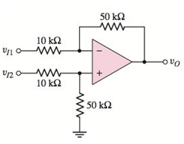
 CMRR dB . (b) Repeat part (a) if the tolerance of each resistor is±3%.

Chapter 14, Problem 14.60P, The opamp in the difference amplifier configuration in Figure P14.60 isideal. (a) If the tolerance
Figure P14.60

a.

Expert Solution
Check Mark
To determine

Minimum value of CMRRdB .

Answer to Problem 14.60P

  CMRRdB(min)=39.96dB

Explanation of Solution

Given:

The given difference amplifier circuit is shown below.

  MICROELECT. CIRCUIT ANALYSIS&DESIGN (LL), Chapter 14, Problem 14.60P , additional homework tip  1

Tolerance of each resistor is ±1.5% .

Calculation:

Circuit with voltage and resistance notation is,

  MICROELECT. CIRCUIT ANALYSIS&DESIGN (LL), Chapter 14, Problem 14.60P , additional homework tip  2

KCL at VY node,

  VYR4+VYv I2R3=0R3VY+R4( V Y v I2 )R4R3=0R3VY+R4(VYv I2)=0(R3+R4)VYR4vI2=0VY=R4R3+R4vI2

As op-amp is ideal, so VX=VY

  VX=R4R3+R4vI2.......(1)

KCL at VX node,

  VXv I1R1+VXv0R2=0R2( V X v I1 )+R1( V X v 0 )R1R2=0R2(VXv I1)+R1(VXv0)=0(R1+R2)VXR2vI1R1v0=0

Now put VX from (1)

  (R1+R2)( R 4 R 3 + R 4 v I2)R2vI1R1v0=0R1v0=(R1+R2)( R 4 R 3 + R 4 )vI2R2vI1v0=( R 1 + R 2 R 1 )( R 4 R 3 + R 4 )vI2R2R1vI1v0=(1+ R 2 R 1 )( R 4 R 3 + R 4 )vI2R2R1vI1

Now,

If vd is differential mode input voltage and vcm is common-mode input voltage. Then,

  vI1=vcmvd2vI2=vcm+vd2v0=(1+ R 2 R 1 )( R 4 R 3 + R 4 )(v cm+ v d 2)R2R1(v cm v d 2).....(2)

For vd=0 and Acm=v0vcm equation (2) results,

  v0=(1+ R 2 R 1 )( R 4 R 3 + R 4 )(v cm+02)R2R1(v cm02)v0=[(1+ R 2 R 1 )( R 4 R 3 + R 4 ) R 2 R 1]vcmv0v cm=(1+ R 2 R 1 )( R 4 R 3 + R 4 )R2R1Acm=(1+ R 2 R 1 )( R 4 R 3 + R 4 )R2R1

For vcm=0 and Ad=v0vd equation (2) results,

  v0=(1+ R 2 R 1 )( R 4 R 3 + R 4 )(0+ v d 2)R2R1(0 v d 2)v0=12[(1+ R 2 R 1 )( R 4 R 3 + R 4 )+ R 2 R 1]vdv0vd=12[(1+ R 2 R 1 )( R 4 R 3 + R 4 )+ R 2 R 1]Ad=12[(1+ R 2 R 1 )( R 4 R 3 + R 4 )+ R 2 R 1]

Now,

  CMRR=| A d A cm|CMRR=12[( 1+ R 2 R 1 )( R 4 R 3 + R 4 )+ R 2 R 1 ]( 1+ R 2 R 1 )( R 4 R 3 + R 4 ) R 2 R 1 CMRR=12[ R 4 R 3 ( 1+ R 2 R 1 ) 1 ( 1+ R 4 R 3 )+ R 2 R 1 ] R 4 R 3 ( 1+ R 2 R 1 )1 ( 1+ R 4 R 3 ) R 2 R 1

For minimum CMRR maximize the denominator i.e. R4R3 will be maximum and R2R1 will be minimum.

  ( R 4 R 3 )max=( 1+1.5% 11.5%)( R 4 R 3 )( R 4 R 3 )max=( 1+ 1.5 100 1 1.5 100 )( 50k 10k)( R 4 R 3 )max=( 1+0.015 10.015)( 50 10)( R 4 R 3 )max=5.152

and

  ( R 2 R 1 )min=( 1+1.5% 11.5%)( R 2 R 1 )( R 2 R 1 )min=( 1+ 1.5 100 1 1.5 100 )( 50k 10k)( R 2 R 1 )min=( 1+0.015 10.015)( 50 10)( R 2 R 1 )min=4.852

Therefore,

  CMRRmin=12[ ( R 4 R 3 ) max( 1+ ( R 2 R 1 ) min ) 1 ( 1+ ( R 4 R 3 ) max )+ ( R 2 R 1 ) min] ( R 4 R 3 ) max( 1+ ( R 2 R 1 ) min )1 ( 1+ ( R 4 R 3 ) max ) ( R 2 R 1 ) min.....(3)CMRRmin=12[5.152(1+4.852) 1 1+5.152+4.852]5.152(1+4.852)1 1+5.1524.852CMRRmin=12[4.901+4.852]4.9014.852CMRRmin=99.52

So, minimum value of CMRRdB is

  CMRRdB(min)=20log10(99.52)CMRRdB(min)=20×1.998CMRRdB(min)=39.96dB

b.

Expert Solution
Check Mark
To determine

Minimum value of CMRRdB .

Answer to Problem 14.60P

  CMRRdB(min)=34dB

Explanation of Solution

Given:

The given difference amplifier circuit is shown below.

  MICROELECT. CIRCUIT ANALYSIS&DESIGN (LL), Chapter 14, Problem 14.60P , additional homework tip  3

Tolerance of each resistor is ±3% .

Calculation:

For tolerance of resistor ±3%

As,

  CMRR=12[ R 4 R 3(1+ R 2 R 1 )1( 1+ R 4 R 3 )+ R 2 R 1]R4R3(1+ R 2 R 1 )1( 1+ R 4 R 3 )R2R1

For minimum CMRR maximize the denominator that is, R4R3 will be maximum and R2R1 will be minimum.

  ( R 4 R 3 )max=( 1+3% 13%)( R 4 R 3 )( R 4 R 3 )max=( 1+ 3 100 1 3 100 )( 50k 10k)( R 4 R 3 )max=( 1+0.03 10.03)( 50 10)( R 4 R 3 )max=5.309

and

  ( R 2 R 1 )min=( 1+3% 13%)( R 2 R 1 )( R 2 R 1 )min=( 1+ 3 100 1 3 100 )( 50k 10k)( R 2 R 1 )min=( 1+0.03 10.03)( 50 10)( R 2 R 1 )min=4.709

Putting the value in equation (3),

  CMRRmin=12[5.309(1+4.709) 1 1+5.309+4.709]5.309(1+4.709)1 1+5.3094.709CMRRmin=12[4.804+4.709]4.8044.709CMRRmin=50.07

So, minimum value of CMRRdB is

  CMRRdB(min)=20log10(50.07)CMRRdB(min)=20×1.7CMRRdB(min)=34dB

Want to see more full solutions like this?

Subscribe now to access step-by-step solutions to millions of textbook problems written by subject matter experts!
Students have asked these similar questions
Explain with neat sketch of close loop (transfer function)
What is the output impedance of Common Emitter Collector Feedback preamplifier whose Collector Resistor is 2.7kohms, Feedback Resistor 180kohms?
Describe the series and shunt input connections of a feedback amplifier.

Chapter 14 Solutions

MICROELECT. CIRCUIT ANALYSIS&DESIGN (LL)

Ch. 14 - Find the closedloop input resistance of a voltage...Ch. 14 - An opamp with openloop parameters of AOL=2105 and...Ch. 14 - A 0.5 V input step function is applied at t=0 to a...Ch. 14 - The slew rate of the 741 opamp is 0.63V/s ....Ch. 14 - Prob. 14.8TYUCh. 14 - Prob. 14.8EPCh. 14 - Consider the active load bipolar duffamp stage in...Ch. 14 - Prob. 14.10EPCh. 14 - Prob. 14.11EPCh. 14 - Prob. 14.12EPCh. 14 - For the opamp circuit shown in Figure 14.28, the...Ch. 14 - Prob. 14.9TYUCh. 14 - List and describe five practical opamp parameters...Ch. 14 - What is atypical value of openloop, lowfrequency...Ch. 14 - Prob. 3RQCh. 14 - Prob. 4RQCh. 14 - Prob. 5RQCh. 14 - Prob. 6RQCh. 14 - Describe the gainbandwidth product property of a...Ch. 14 - Define slew rate and define fullpower bandwidth.Ch. 14 - Prob. 9RQCh. 14 - What is one cause of an offset voltage in the...Ch. 14 - Prob. 11RQCh. 14 - Prob. 12RQCh. 14 - Prob. 13RQCh. 14 - Prob. 14RQCh. 14 - Prob. 15RQCh. 14 - Prob. 16RQCh. 14 - Prob. 17RQCh. 14 - Prob. 14.1PCh. 14 - Consider the opamp described in Problem 14.1. In...Ch. 14 - Data in the following table were taken for several...Ch. 14 - Prob. 14.4PCh. 14 - Prob. 14.5PCh. 14 - Prob. 14.6PCh. 14 - Prob. 14.7PCh. 14 - Prob. 14.8PCh. 14 - An inverting amplifier is fabricated using 0.1...Ch. 14 - For the opamp used in the inverting amplifier...Ch. 14 - Prob. 14.11PCh. 14 - Consider the two inverting amplifiers in cascade...Ch. 14 - The noninverting amplifier in Figure P14.13 has an...Ch. 14 - For the opamp in the voltage follower circuit in...Ch. 14 - The summing amplifier in Figure P14.15 has an...Ch. 14 - Prob. 14.16PCh. 14 - Prob. 14.18PCh. 14 - Prob. 14.19PCh. 14 - Prob. 14.20PCh. 14 - Prob. 14.21PCh. 14 - Prob. 14.22PCh. 14 - Three inverting amplifiers, each with R2=150k and...Ch. 14 - Prob. 14.24PCh. 14 - Prob. 14.25PCh. 14 - Prob. 14.26PCh. 14 - Prob. 14.27PCh. 14 - Prob. D14.28PCh. 14 - Prob. 14.29PCh. 14 - Prob. 14.30PCh. 14 - Prob. 14.31PCh. 14 - Prob. 14.32PCh. 14 - Prob. 14.33PCh. 14 - Prob. 14.34PCh. 14 - Prob. 14.35PCh. 14 - Prob. 14.36PCh. 14 - Prob. 14.37PCh. 14 - In the circuit in Figure P14.38, the offset...Ch. 14 - Prob. 14.39PCh. 14 - Prob. 14.40PCh. 14 - Prob. 14.41PCh. 14 - Prob. 14.42PCh. 14 - Prob. 14.43PCh. 14 - Prob. 14.44PCh. 14 - Prob. 14.46PCh. 14 - Prob. D14.47PCh. 14 - Prob. 14.48PCh. 14 - Prob. 14.50PCh. 14 - Prob. 14.51PCh. 14 - Prob. D14.52PCh. 14 - Prob. D14.53PCh. 14 - Prob. 14.55PCh. 14 - Prob. 14.56PCh. 14 - Prob. 14.57PCh. 14 - The opamp in the difference amplifier...Ch. 14 - Prob. 14.61P
Knowledge Booster
Background pattern image
Electrical Engineering
Learn more about
Need a deep-dive on the concept behind this application? Look no further. Learn more about this topic, electrical-engineering and related others by exploring similar questions and additional content below.
Recommended textbooks for you
Text book image
Introductory Circuit Analysis (13th Edition)
Electrical Engineering
ISBN:9780133923605
Author:Robert L. Boylestad
Publisher:PEARSON
Text book image
Delmar's Standard Textbook Of Electricity
Electrical Engineering
ISBN:9781337900348
Author:Stephen L. Herman
Publisher:Cengage Learning
Text book image
Programmable Logic Controllers
Electrical Engineering
ISBN:9780073373843
Author:Frank D. Petruzella
Publisher:McGraw-Hill Education
Text book image
Fundamentals of Electric Circuits
Electrical Engineering
ISBN:9780078028229
Author:Charles K Alexander, Matthew Sadiku
Publisher:McGraw-Hill Education
Text book image
Electric Circuits. (11th Edition)
Electrical Engineering
ISBN:9780134746968
Author:James W. Nilsson, Susan Riedel
Publisher:PEARSON
Text book image
Engineering Electromagnetics
Electrical Engineering
ISBN:9780078028151
Author:Hayt, William H. (william Hart), Jr, BUCK, John A.
Publisher:Mcgraw-hill Education,
Power System Stability in C# Part 1: Fundamentals of Stability Analysis; Author: EETechStuff;https://www.youtube.com/watch?v=SaT9oWcHgKw;License: Standard Youtube License