
Videos
Using the circuit and transistor parameters of Example 13.11, and assuming threshold voltages of
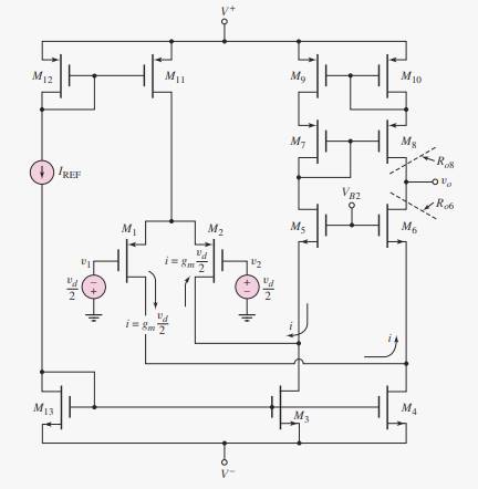
The maximum range of the common mode input voltage.
Answer to Problem 14.1TYU
Explanation of Solution
Given information:
Transistor parameters are:
Threshold voltage is
The given circuit is shown below.
Calculation:
The common mode input voltage range is given by
Let
For M1
Substituting the values,
Similarly for M4
Substituting the values,
Want to see more full solutions like this?
Chapter 14 Solutions
MICROELECT. CIRCUIT ANALYSIS&DESIGN (LL)
Additional Engineering Textbook Solutions
Introductory Circuit Analysis (13th Edition)
Electric Circuits. (11th Edition)
Basic Engineering Circuit Analysis
ANALYSIS+DESIGN OF LINEAR CIRCUITS(LL)
Principles and Applications of Electrical Engineering
Engineering Electromagnetics


- Using 741 op amp, design a suitable circuit to generate Binary Phase Shift Keyiing(BFSK) modulator. Design should perform in such a way that the BFSK output should contain a frequency of f1=2kHz when message signal is low and f2 =4kHz when the message signal is high. Take the frequency of message signal as 200Hz. Draw the clear circuit diagram and calculate the values of resistors and capacitors used.arrow_forwardConsider the common-source amplifier shown in Figure P11.50. The NMOS transistor has KP=50 μA/V2, L=5 μm, W=500 μm, Vto=1 V and rd=∞.a. Determine the values of IDQ, VDSQ and gm. b. Compute the voltage gain, input resistance, and output resistance, assuming that the coupling capacitors are short circuits for the ac signal. Repeat Problem P11.50 for an NMOS transistor having KP=50 μA/V2, W=600 μm, L=20 μm, Vto=2 V and rd=∞. Compare the gain with that attained in Problem P11.50.arrow_forwardThe transistor parameters for the differential amplifier shown in Figure P11.32 are VT N = 0.5 V, k n = 80 µA/V2, W/L = 4, and λ = 0. (a) Find RD and IQ such that ID1 = ID2 = 80 µA and vO2 = 2 V when v1 = v2 = 0. (b) Draw the dc load line, and plot the Q-point for M2. (c) What is the maximum common-mode input voltage? Figure p11.32arrow_forward
- 1. Describe the high frequency response and phase shift for BJT and FET transistors using MillersTheorem ata) Input RC circuitb) Output RC circuit The subject : Analogue Electronics IIarrow_forward1: Determine the collector current IC of Q1 for the circuit shown below.arrow_forwardGiven the differential amplifier circuit below. Determine the following: emitter current, differential mode voltage gain, common mode voltage gain and CMRR.arrow_forward
- (b)A pulse of amplitide V is applied to vIN at time t=0 seconds for ΔT seconds. Find an expression for the time t1 at which the MOSFET M2 turns off in terms of the circuit and MOSFET parameters, assuming t1< ΔT.arrow_forwardQ18.Determine the values of VCE(off) and IC(sat) for the circuit shown in the figure.arrow_forwardTopic: Input and Output Characteristics of Transistor in Common Base Configuration Answer in 2-3 sentences each. Need a kind tutor that will do it for me. Thank you! 1. What are the applications of the common base (CB) configuration? 2. What are the output and input impedances of CB configuration?arrow_forward
- For the differential amplifier circuit below, all transistors are identical ( ?≠0 ) a) Draw the single-sided differential mode equivalent circuit, showing all details and labels Explain how you obtained this equivalent circuitarrow_forwardDescription and discussion of Discussed active band pass filter in the circuit belowarrow_forwardThe Type K thermocouple has a sensitivity of about 41 micro-Volts/℃, i.e. for each degree difference in the junction temperature, the output changes by 41 micro-Volts. Among 8-bit, 12-bit, 16-bit, 32-bit and 64-bit ADC, which is the most appropriate for measuring human body temperature to 4th decimal place (appropriate = accurate yet cost-effective), if the ADC range is 10 V?arrow_forward
 Introductory Circuit Analysis (13th Edition)Electrical EngineeringISBN:9780133923605Author:Robert L. BoylestadPublisher:PEARSON
 Delmar's Standard Textbook Of ElectricityElectrical EngineeringISBN:9781337900348Author:Stephen L. HermanPublisher:Cengage Learning
 Programmable Logic ControllersElectrical EngineeringISBN:9780073373843Author:Frank D. PetruzellaPublisher:McGraw-Hill Education
 Fundamentals of Electric CircuitsElectrical EngineeringISBN:9780078028229Author:Charles K Alexander, Matthew SadikuPublisher:McGraw-Hill Education
 Electric Circuits. (11th Edition)Electrical EngineeringISBN:9780134746968Author:James W. Nilsson, Susan RiedelPublisher:PEARSON
 Engineering ElectromagneticsElectrical EngineeringISBN:9780078028151Author:Hayt, William H. (william Hart), Jr, BUCK, John A.Publisher:Mcgraw-hill Education,