Concept explainers
Videos
Ruby, with mass 55.0 kg, is trying to reach a box on a high shelf by standing on her tiptoes. In this position, half her weight is supported by the normal force exerted by the floor on the toes of each foot as shown in Figure P14.75A. This situation can be modeled mechanically by representing the force on Ruby’s Achilles tendon with
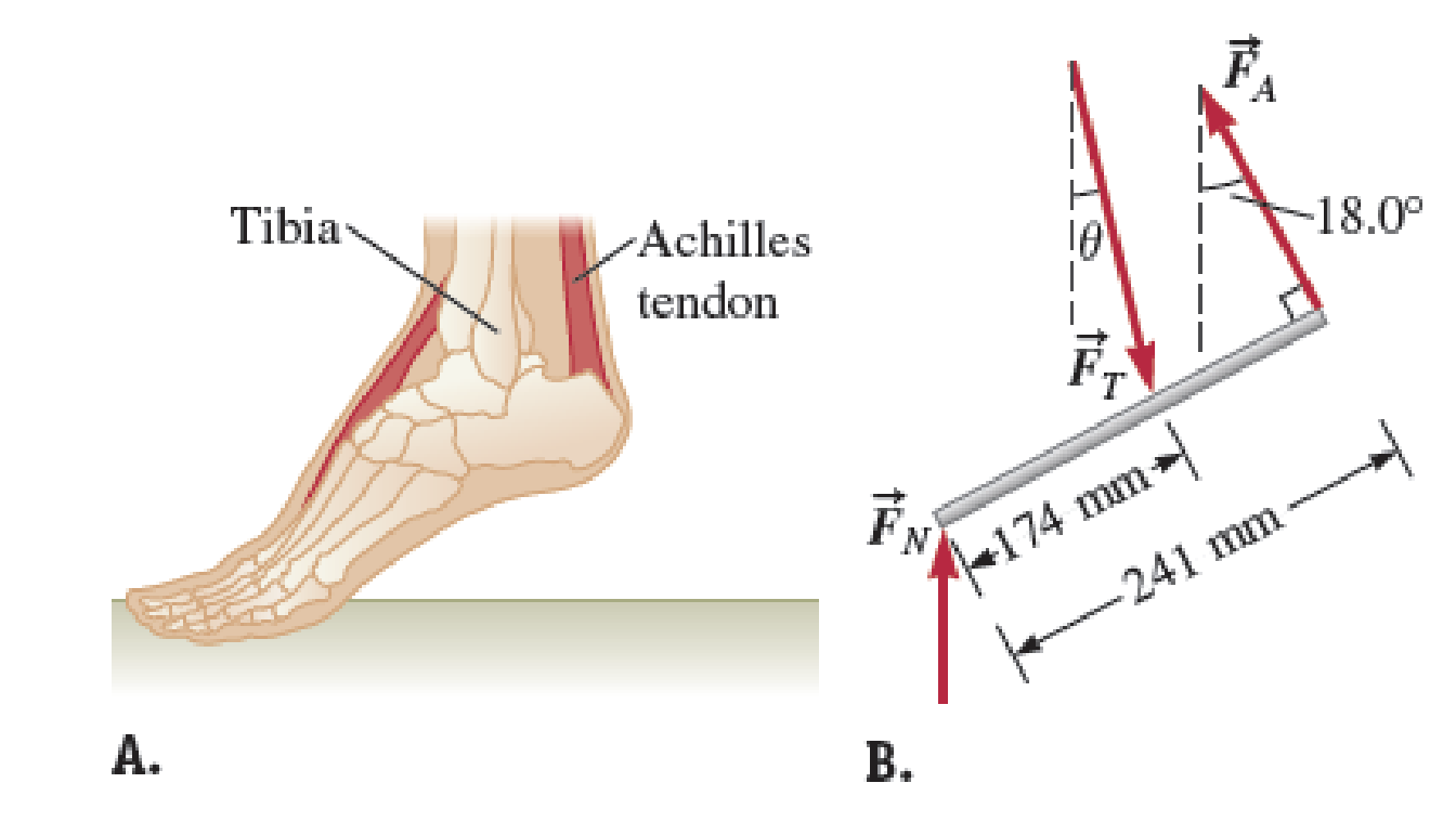
FIGURE P14.75
Want to see the full answer?
Check out a sample textbook solution
Chapter 14 Solutions
Physics for Scientists and Engineers: Foundations and Connections


- A 500-N uniform rectangular sign 4.00 m wide and 3.00 m high is suspended from a horizontal, 6.00-m-long, uniform. 100-N rod as indicated in Figure P12.47. The left end of the rod is supported by a hinge, and the right end is supported by a thin cable making a 30.0 angle with the vertical. (a) Find the tension T in the cable. (b) Find the horizontal and vertical components of force exerted on the left end of the rod by the hinge. Figure P12.47arrow_forwardWhen a circus performer performing on the rings executes the iron cross, he maintains the position at rest shown in Figure P12.37a. In this maneuver, the gymnasts feet (not shown) are off the floor. The primary muscles involved in supporting this position are the latissimus dorsi (lats) and the pectoralis major (pecs). One of the rings exerts an upward force Fk on a hand as show n in Figure P12.37b. The force Fs, is exerted by the shoulder joint on the arm. The latissimus dorsi and pectoralis major muscles exert a total force Fm on the arm. (a) Using the information in the figure, find the magnitude of the force Fm for an athlete of weight 750 N. (b) Suppose a performer in training cannot perform the iron cross but can hold a position similar to the figure in which the arms make a 45 angle with the horizontal rather than being horizontal. Why is this position easier for the performer? Figure P12.37arrow_forwardA horizontal, rigid bar of negligible weight is fixed against a vertical wall at one end and supported by a vertical string at the other end. The bar has a length of 50.0 cm and is used to support a hanging block of weight 400.0 N from a point 30.0 cm from the wall as shown in Figure P14.81. The string is made from a material with a tensile strength of 1.2 108 N/m2. Determine the largest diameter of the string for which it would still break. FIGURE P14.81arrow_forward
- A uniform sign of weight Fg and width 2L hangs from a light, horizontal beam hinged at the wall and supported by a cable (Fig. P12.31). Determine (a) the tension in the cable and (b) the components of the reaction force exerted by the wall on the beam in terms of Fg, d, L, and . Figure P12.31arrow_forwardWhen a person stands on tiptoe on one foot (a strenuous position), the position of the foot is as shown in Figure P12.32a. The total gravitational force Fg on the body is supported by the normal force n exerted by the floor on the toes of one foot. A mechanical model of the situation is shown in Figure P12.32b, where T is the force exerted on the foot by the Achilles tendon and R is the force exerted on the foot by the tibia. Find the values of T, R, and when Fg = 700 N. Figure P12.32arrow_forwardA stepladder of negligible weight is constructed as shown in Figure P12.40, with AC = BC = . A painter of mass m stands on the ladder a distance d from the bottom. Assuming the floor is frictionless, find (a) the tension in the horizontal bar DE connecting the two halves of the ladder, (b) the normal forces at A and B, and (c) the components of the reaction force at the single hinge C that the left half of the ladder exerts on the right half. Suggestion: Treat the ladder as a single object, but also treat each half of the ladder separately. Figure P12.40 Problems 40 and 41.arrow_forward
- A 10 000-N shark is supported by a rope attached to a 4.00-m rod that can pivot at the base. (a) Calculate the tension in the cable between the rod and the wall, assuming the cable is holding the system in the position shown in Figure P12.33. Find (b) the horizontal force and (c) the vertical force exerted on the base of the rod. Ignore the weight of the rod. Figure P12.33arrow_forwardA bridge of length 50.0 m and mass 8.00 104 kg is supported on a smooth pier at each end as shown in Figure P12.25. A truck of mass 3.00 104 kg is located 15.0 m from one end. What are the forces on the bridge at the points of support? Figure P12.25arrow_forwardThree forces are exerted on the disk shown in Figure P12.71,and their magnitudes are F3 = 2F2 = 2F1. The disks outer rimhas radius R, and the inner rim has radius R/2. As shown in thefigure, F1 and F3 are tangent to the outer rim of the disk, and F2 is tangent to the inner rim. F3 is parallel to the x axis, F2 is parallel to the y axis, and F1 makes a 45 angle with the negative x axis. Find expressions for the magnitude of each torque exertedaround the center of the disk in terms of R and F1. FIGURE P12.71 Problems 71-75arrow_forward
- Figure P12.38 shows a light truss formed from three struts lying in a plane and joined by three smooth hinge pins at their ends. The truss supports a downward force of F=1000N applied at the point B. The truss has negligible weight. The piers at A and C are smooth. (a) Given 1 = 30.0 and 2 = 45.0, find nA and nC. (b) One can show that the force any strut exerts on a pin must be directed along the length of the strut as a force of tension or compression. Use that fact to identify the directions of the forces that the struts exert on the pins joining them. Find the force of tension or of compression in each of the three bars. Figure P12.38arrow_forwardConsider a nanotube with a Youngs modulus of 2.130 1012 N/m2 that experiences a tensile stress of 5.3 1010 N/m2. Steel has a Youngs modulus of about 2.000 1011 Pa. How much stress would cause a piece of steel to experience the same strain as the nanotube?arrow_forwardWhy is the following situation impossible? A uniform beam of mass mk = 3.00 kg and length = 1.00 m supports blocks with masses m1 = 5.00 kg and m2 = 15.0 kg at two positions as shown in Figure P12.2. The beam rests on two triangular blocks, with point P a distance d = 0.300 m to the right of the center of gravity of the beam. The position of the object of mass m2 is adjusted along the length of the beam until the normal force on the beam at O is zero. Figure P12.2arrow_forward
 Physics for Scientists and Engineers: Foundations...PhysicsISBN:9781133939146Author:Katz, Debora M.Publisher:Cengage Learning
 Physics for Scientists and Engineers with Modern ...PhysicsISBN:9781337553292Author:Raymond A. Serway, John W. JewettPublisher:Cengage Learning
 Physics for Scientists and EngineersPhysicsISBN:9781337553278Author:Raymond A. Serway, John W. JewettPublisher:Cengage Learning