
EBK STATICS AND MECHANICS OF MATERIALS
5th Edition
ISBN: 8220102955295
Author: HIBBELER
Publisher: PEARSON
expand_more
expand_more
format_list_bulleted
Concept explainers
Videos
Textbook Question
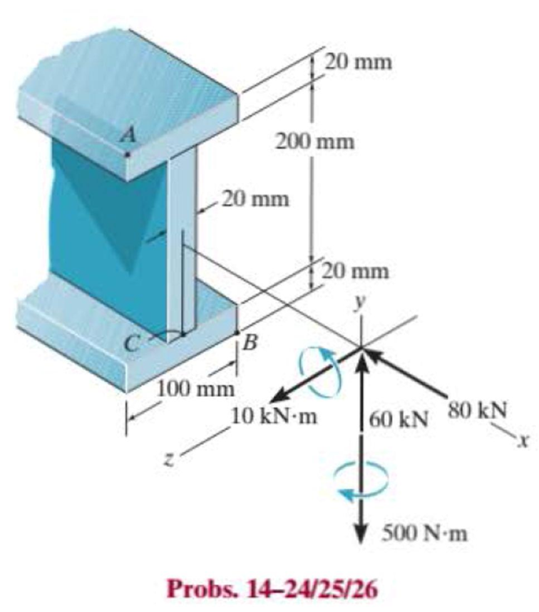
Chapter 14.3, Problem 26P
The internal loadings at a section of the beam are shown. Determine the in-plane principal stresses at point A. Also compute the maximum in-plane shear stress at this point.
14–26. Solve Prob. 14–24 for point C.
Expert Solution & Answer
Want to see the full answer?
Check out a sample textbook solution
Students have asked these similar questions
In each case, the state of stress sx, sy, txy produces normal and shear stress components along section AB of the element that have values of sx = -5 kPa and tx y = 8 kPa when calculated using the stress transformation equations.Establish the x and y axes for each segment and specify the angle u, then show these results acting on each segment.
Determine the maximum tensile and compressive stresses in portion BC
of the beam, under loading conditions of two vertical forces that applied
on it. The beam has cross section as shown in figure.
100KN
| 100KN
200
mm
25 mm
25 mm
150 um
25 mm
1500 mm
500 mm
500 mm
100 mm
The hook is subjected to the force of 80 lb. Determine the state of stress at point B at section a–a. The cross section has a diameter of 0.5 in. Use the curved-beam formula to calculate the bending stress.
Chapter 14 Solutions
EBK STATICS AND MECHANICS OF MATERIALS
Ch. 14.3 - In each ease, the state of stress x, y, xy...Ch. 14.3 - Given the state of stress shown on the element,...Ch. 14.3 - Determine the normal stress and shear stress...Ch. 14.3 - Prob. 2FPCh. 14.3 - Determine the equivalent state of stress on an...Ch. 14.3 - Prob. 4FPCh. 14.3 - The beam is subjected to the load at its end....Ch. 14.3 - Prob. 6FPCh. 14.3 - Prove that the sum of the normal stresses x+y=x+y...Ch. 14.3 - Determine the stress components acting on the...
Ch. 14.3 - Determine the stress components acting on the...Ch. 14.3 - Determine the normal stress and shear stress...Ch. 14.3 - Determine the normal stress and shear stress...Ch. 14.3 - Prob. 6PCh. 14.3 - Prob. 7PCh. 14.3 - Determine the stress components acting on the...Ch. 14.3 - Determine the stress components acting on the...Ch. 14.3 - Determine the stress components acting on the...Ch. 14.3 - Determine the equivalent state of stress on an...Ch. 14.3 - Prob. 12PCh. 14.3 - Determine the stress components acting on the...Ch. 14.3 - Determine (a) the principal stresses and (b) the...Ch. 14.3 - Prob. 15PCh. 14.3 - Prob. 16PCh. 14.3 - Prob. 17PCh. 14.3 - Prob. 18PCh. 14.3 - Prob. 19PCh. 14.3 - Prob. 20PCh. 14.3 - Prob. 21PCh. 14.3 - The state of stress at a point in a member is...Ch. 14.3 - The wood beam is subjected to a load of 12 kN. If...Ch. 14.3 - Prob. 24PCh. 14.3 - The internal loadings at a section of the beam are...Ch. 14.3 - The internal loadings at a section of the beam are...Ch. 14.3 - Prob. 27PCh. 14.3 - Prob. 28PCh. 14.3 - The beam has a rectangular cross section and is...Ch. 14.3 - A paper tube is formed by rolling a cardboard...Ch. 14.3 - Prob. 31PCh. 14.3 - The 2-in.-diameter drive shaft AB on the...Ch. 14.3 - Determine the principal stresses in the...Ch. 14.3 - The internal loadings at a cross section through...Ch. 14.3 - The internal loadings at a cross section through...Ch. 14.3 - Prob. 36PCh. 14.3 - The steel pipe has an inner diameter of 2.75 in....Ch. 14.3 - Prob. 38PCh. 14.3 - The wide-flange beam is subjected to the 50-kN...Ch. 14.3 - Prob. 40PCh. 14.3 - The box beam is subjected to the 26-kN force that...Ch. 14.3 - The box beam is subjected to the 26-kN force that...Ch. 14.4 - Use Mohrs circle to determine the normal stress...Ch. 14.4 - Prob. 8FPCh. 14.4 - Prob. 9FPCh. 14.4 - Prob. 10FPCh. 14.4 - Prob. 11FPCh. 14.4 - Prob. 12FPCh. 14.4 - Solve Prob. 142 using Mohrs circle. 14-2.Determine...Ch. 14.4 - Solve Prob. 143 using Mohrs circle. 143.Determine...Ch. 14.4 - Determine the stress components acting on the...Ch. 14.4 - Solve Prob. 1410 using Mohrs circle. 149.Determine...Ch. 14.4 - Solve Prob. 1415 using Mohrs circle. 1415.The...Ch. 14.4 - Solve Prob. 1416 using Mohrs circle....Ch. 14.4 - Prob. 49PCh. 14.4 - Determine (a) the principal stresses and (b) the...Ch. 14.4 - Determine (a) the principal stresses and (b) the...Ch. 14.4 - Determine the equivalent state of stress if an...Ch. 14.4 - Draw Mohrs circle that describes each of the...Ch. 14.4 - Draw Mohrs circle that describes each of the...Ch. 14.4 - Determine (a) the principal stresses and (b) the...Ch. 14.4 - Determine (a) the principal stress and (b) the...Ch. 14.4 - Determine (a) the principal stresses and (b) the...Ch. 14.4 - Determine (a) the principal stresses and (b) the...Ch. 14.4 - Determine (a) the principal stresses and (b) the...Ch. 14.4 - Prob. 60PCh. 14.4 - The grains of wood in the board make an angle of...Ch. 14.4 - The post is fixed supported at its base and a...Ch. 14.4 - Determine the principal stresses, the maximum...Ch. 14.4 - The thin-walled pipe has an inner diameter of 0.5...Ch. 14.4 - The frame supports the triangular distributed load...Ch. 14.4 - The frame supports the triangular distributed load...Ch. 14.4 - Prob. 67PCh. 14.4 - The pedal crank for a bicycle has the cross...Ch. 14.4 - A spherical pressure vessel has an inner radius of...Ch. 14.4 - The cylindrical pressure vessel has an inner...Ch. 14.4 - Prob. 71PCh. 14.4 - Determine the principal stress at point D, which...Ch. 14.4 - If the box wrench is subjected to the 50 lb force,...Ch. 14.4 - If the box wrench is subjected to the 50-lb force,...Ch. 14.4 - Prob. 75PCh. 14.5 - Draw the three Mohrs circles that describe each of...Ch. 14.5 - Draw the three Mohrs circles that describe the...Ch. 14.5 - Draw the three Mohrs circles that describe the...Ch. 14.5 - Determine the principal stresses and the absolute...Ch. 14.5 - Prob. 80PCh. 14.5 - Prob. 81PCh. 14.5 - Prob. 82PCh. 14.8 - Prove that the sum of the normal strains in...Ch. 14.8 - The state of strain at the point on the arm has...Ch. 14.8 - The state of strain at the point on the pin leaf...Ch. 14.8 - The state of strain at the point on the pin leaf...Ch. 14.8 - Prob. 88PCh. 14.8 - The state of strain at a point on the bracket has...Ch. 14.8 - Prob. 90PCh. 14.8 - Prob. 91PCh. 14.8 - Prob. 92PCh. 14.8 - Prob. 93PCh. 14.8 - Prob. 94PCh. 14.8 - Prob. 95PCh. 14.8 - Prob. 96PCh. 14.8 - Prob. 97PCh. 14.8 - The state of strain on the element has components...Ch. 14.8 - Solve Prob. 1486 using Mohrs circle. 1486.The...Ch. 14.8 - Solve Prob. 1487 using Mohrs circle. 1486.The...Ch. 14.8 - Solve Prob. 1488 using Mohrs circle. 1488.The...Ch. 14.8 - Solve Prob. 1491 using Mohrs circle. 1491.The...Ch. 14.8 - Solve Prob. 1490 using Mohrs circle. 1489.The...Ch. 14.11 - The strain at point A on the bracket has...Ch. 14.11 - The strain at point A on a beam has components...Ch. 14.11 - The strain at point A on the pressure-vessel wall...Ch. 14.11 - The 45 strain rosette is mounted on the surface of...Ch. 14.11 - Prob. 109PCh. 14.11 - Use Hookes law, Eq. 1432, to develop the strain...Ch. 14.11 - Prob. 111PCh. 14.11 - A rod has a radius of 10 mm. If it is subjected to...Ch. 14.11 - The polyvinyl chloride bar is subjected to an...Ch. 14.11 - The polyvinyl chloride bar is subjected to an...Ch. 14.11 - The spherical pressure vessel has an inner...Ch. 14.11 - Determine the bulk modulus for each of the...Ch. 14.11 - The strain gage is placed on the surface of the...Ch. 14.11 - The principal strains at a point on the aluminum...Ch. 14.11 - Prob. 119PCh. 14.11 - Prob. 120PCh. 14.11 - The cube of aluminum is subjected to the three...Ch. 14.11 - The principal strains at a point on the aluminum...Ch. 14.11 - A uniform edge load of 500 lb/in. and 350 lb/in....Ch. 14.11 - Prob. 124PCh. 14 - The steel pipe has an inner diameter of 2.75 in....Ch. 14 - Prob. 2RPCh. 14 - Prob. 3RPCh. 14 - The crane is used to support the 350-lb load....Ch. 14 - In the case of plane stress, where the in-plane...Ch. 14 - The plate is made of material having a modulus of...Ch. 14 - If the material is graphite for which Eg = 800 ksi...Ch. 14 - A single strain gage, placed in the vertical plane...Ch. 14 - The 60 strain rosette is mounted on a beam. The...
Knowledge Booster


Learn more about
Need a deep-dive on the concept behind this application? Look no further. Learn more about this topic, mechanical-engineering and related others by exploring similar questions and additional content below.Similar questions
- 2. determine the maximum normal stress and the maximum shear stress at point O in dia. B 15 in 7 in F = 15 lbfarrow_forwardThe wide-flange beam is subjected to the P = 54 kN force. Determine the principal stresses in the beam at point A located on the web at the bottom of the upper flange. Although it is not very accurate, use the shear formula to calculate the shear stress. (Figure 1)arrow_forward6kN and 1.0KNM loads are applied to the top of the 62-mm-diameter cast-iron as shown. Determine the principal stresses (max and min normal stresses), principal planes (orientation of plane for max-min normal stresses) and max shear stress by using Mohr's circle. Hint: Use given coordinate system. So, H is on x-z plane and K is on y- z plane 1.0 kN.m 6 kN X 220 mmarrow_forward
- Determine the maximum tensile and compressive stresses in portion BC of the beam, under loading conditions of two vertical forces that applied on it. The beam has cross section as shown in figure. 100KN 100KN 200 B 25 m 25 mm 150 m mm -1500 mm 500 mm 500 mm 100 mmarrow_forwardX A purse hook is used to hang a handbag from the edge of a table with L = 50 mm. If the cross section at a-a has a diameter of d = 3 mm and the hook is supporting a purse with a mass of 3 kg, determine the normal stress profile. For what value of y (using the coordinates pictured for section a-a) with the normal stress be zero. If it is never zero enter "nde" for "not defined". N -L→ a. a AB C Follow sign convention that tension is positive and compression is negative. Normal stress at point A, σA= MPa Normal stress at point B, σB = MPa Normal stress at point C, σc = MPa y position where normal stress equals zero = mm Section a-a darrow_forwardThe internal loadings at a section of the beam are shown. Determine the in-plane principal stresses at point A. Also, compute the maximum in-plane shear stress at this point.arrow_forward
- Two blocks joined by a single pin are subjected to a pulling force of P = 250 Ib. The pin has a diameter of 0.25 in and the dimensions of the blocks with respect to the figure below are listed below. a = 2.42 in b = 1.52 in C = 1.5 in ti = 0.89 in t2 = 1.2 in Note that the dimensions b and c represent the distance from the edge of the block to the middle of the pin t, 1 a Vinter201920-Engr220-001/images/9de8f780-b478-3fb6-91f7-bd1015381538_fafc4bb4-e5d Image is not drawn to scale.arrow_forwardThe block is subjected to the eccentric load shown. Sketch the normal-stress distribution acting over the cross section at section a–a. Neglect the weight of the block.arrow_forwardDo neatlyarrow_forward
- The wide-flange beam is subjected to the 50-kN force. Determine the principal stresses in the beam at point A located on the web at the bottom of the upper flange. Although it is not very accurate, use the shear formula tocalculate the shear stress.arrow_forwardA load of 3 kN is applied to a cantilever beam as shown below. The force can be resolved into a horizontal and vertical force component acting on the top of the beam, which results in combined loading conditions. The side view (elevation) and cross section of the beam are shown below. Determine the normal stress and shear stress at the mid-height of the vertical components of the beam cross section at section a-a. Note that the neutral axis location does not need to be calculated as it is provided for you in the cross section. Enter the normal stress rounded to the nearest kPa. In your written work, also include the shear stress value rounded to the nearest kPa.arrow_forwardA rod has a solid circular cross section with a diameter of 40 mm is subjected to the shown loads. Determine the state of stress at point A. OX= Ixy = Given: The area moment of inertia of a solid circular cross section about its neutral axis is INA = (TR4)/4. The polar moment of inertia of a solid circular cross section about its neutral axis is JNA = (TR4)/2. The centroid of a semi-circle is located at 4R/(3n) from the horizontal axis representing the diameter line. 1500 N -37 Mpa 64 Mpa 3.5 Mpa 7.3 Mpa 600 N 37 Mpa -7.3 Mpa 300 mm 100 N·m 800 N 100 mm Barrow_forward
arrow_back_ios
SEE MORE QUESTIONS
arrow_forward_ios
Recommended textbooks for you
 Elements Of ElectromagneticsMechanical EngineeringISBN:9780190698614Author:Sadiku, Matthew N. O.Publisher:Oxford University Press
 Mechanics of Materials (10th Edition)Mechanical EngineeringISBN:9780134319650Author:Russell C. HibbelerPublisher:PEARSON
 Thermodynamics: An Engineering ApproachMechanical EngineeringISBN:9781259822674Author:Yunus A. Cengel Dr., Michael A. BolesPublisher:McGraw-Hill Education
 Control Systems EngineeringMechanical EngineeringISBN:9781118170519Author:Norman S. NisePublisher:WILEY
 Mechanics of Materials (MindTap Course List)Mechanical EngineeringISBN:9781337093347Author:Barry J. Goodno, James M. GerePublisher:Cengage Learning
 Engineering Mechanics: StaticsMechanical EngineeringISBN:9781118807330Author:James L. Meriam, L. G. Kraige, J. N. BoltonPublisher:WILEY
Elements Of Electromagnetics
Mechanical Engineering
ISBN:9780190698614
Author:Sadiku, Matthew N. O.
Publisher:Oxford University Press
Mechanics of Materials (10th Edition)
Mechanical Engineering
ISBN:9780134319650
Author:Russell C. Hibbeler
Publisher:PEARSON
Thermodynamics: An Engineering Approach
Mechanical Engineering
ISBN:9781259822674
Author:Yunus A. Cengel Dr., Michael A. Boles
Publisher:McGraw-Hill Education
Control Systems Engineering
Mechanical Engineering
ISBN:9781118170519
Author:Norman S. Nise
Publisher:WILEY
Mechanics of Materials (MindTap Course List)
Mechanical Engineering
ISBN:9781337093347
Author:Barry J. Goodno, James M. Gere
Publisher:Cengage Learning
Engineering Mechanics: Statics
Mechanical Engineering
ISBN:9781118807330
Author:James L. Meriam, L. G. Kraige, J. N. Bolton
Publisher:WILEY
Understanding Torsion; Author: The Efficient Engineer;https://www.youtube.com/watch?v=1YTKedLQOa0;License: Standard YouTube License, CC-BY