
Fundamentals of Geotechnical Engineering (MindTap Course List)
5th Edition
ISBN: 9781305635180
Author: Braja M. Das, Nagaratnam Sivakugan
Publisher: Cengage Learning
expand_more
expand_more
format_list_bulleted
Concept explainers
Videos
Textbook Question
Chapter 15, Problem 15.17P
For the braced cut described in Problem 15.16, assume that σall = 170 MN/m2.
- a. Determine the sheet pile section (section modulus)
- b. What is the section modulus of the wales at level A?
15.16 Refer to the braced cut in Figure 15.50, for which γ = 17 kN/m3, ϕ′ = 30°, and c′ = 0. The struts are located at 3 m on center in the plan. Draw the earth pressure envelope and determine the strut loads at levels A, B, and C.
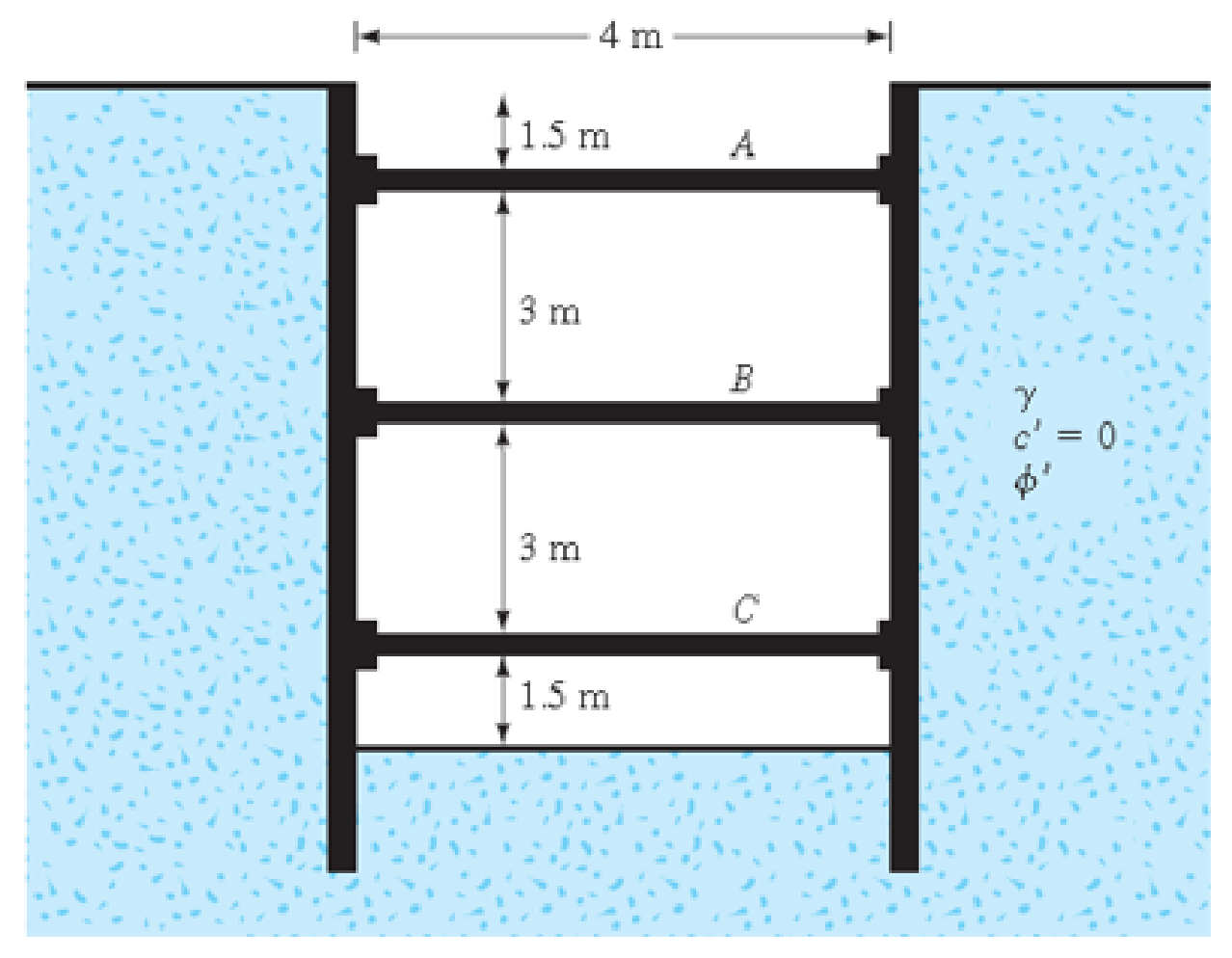
FIG. 15.50
Expert Solution & Answer

Trending nowThis is a popular solution!

Students have asked these similar questions
An anchored sheet-pile bulkhead is shown in Figure P14.10. Let L1 = 2 m, L2 = 6 m, l1 = 1 m, γ = 16 kN/m3, γsat = 18.86 kN/m3, Φ' = 32º, and c = 27 kN/m2.a. Determine the theoretical depth of embedment, D.b. Calculate the anchor force per unit length of the sheet-pile wall. Use the free earth support method.
Refer to the braced cut shown below. Given: unit weight = 17 kN/m3, Friction angle = 35degrees, and c = 0. The struts are located at 3 m center-to-center in the plan. a. Draw the earth-pressure envelope and determine the strut loads at levels A, B, and C. b. Determine the sheet-pile section modulus c. Determine the section modulus of the wales at level B Assume that = 170 MN/m2.
The cross section of a braced cut supporting a sheet pile installation in a clay soil is shown in the figure
below. Given: H = 12 m , clay = 17.9 kN/m3
, = 0 , C = 75 kN/m2
, and the center-to-center spacing of
struts in plan view , S = 3 m.
Chapter 15 Solutions
Fundamentals of Geotechnical Engineering (MindTap Course List)
Ch. 15 - Prob. 15.1PCh. 15 - Prob. 15.2PCh. 15 - Prob. 15.3PCh. 15 - Prob. 15.4PCh. 15 - Prob. 15.5PCh. 15 - Prob. 15.6PCh. 15 - Prob. 15.7PCh. 15 - Prob. 15.8PCh. 15 - Prob. 15.9PCh. 15 - Prob. 15.10P
Ch. 15 - Prob. 15.11PCh. 15 - Prob. 15.12PCh. 15 - Prob. 15.13PCh. 15 - Prob. 15.14PCh. 15 - Prob. 15.15PCh. 15 - Refer to the braced cut in Figure 15.50, for which...Ch. 15 - For the braced cut described in Problem 15.16,...Ch. 15 - Refer to Figure 15.51 in which = 17.5 kN/m3, c =...Ch. 15 - Refer to Figure 15.27a. For the braced cut, H = 6...Ch. 15 - Prob. 15.20PCh. 15 - Determine the factor of safety against bottom...Ch. 15 - Prob. 15.22PCh. 15 - The water table at a site is at 5 m below the...Ch. 15 - Prob. 15.24PCh. 15 - Prob. 15.25CTPCh. 15 - Figure 15.53 below shows a cantilever sheet pile...
Knowledge Booster


Learn more about
Need a deep-dive on the concept behind this application? Look no further. Learn more about this topic, civil-engineering and related others by exploring similar questions and additional content below.Similar questions
- The cross section of a braced cut supporting a sheet pile installation in a clay soil is shown in Figure 14.22. Given: H = 12 m, clay = 17.9 kN/m3, = 0, c = 75 kN/m2, and the center-to-center spacing of struts in plan view, s = 3 m. a. Using Pecks empirical pressure diagrams, draw the earth-pressure envelope. b. Determine the strut loads at levels A, B, and C.arrow_forwardA 5 m wide braced excavation is made in a saturated clay, as shown in Figure P19.1, with the following properties: c = 20 kN/m2, = 0, and = 18.5 kN/m3. The struts are spaced at 5 m center to center in plan. a. Determine the strut forces. b. Determine the section modulus of the sheet pile required, assuming all = 170 MN/m2. c. Determine the maximum moment for the wales at levels B and C.arrow_forwardA braced cut shown in Figure P19.3 is to be made to a depth of 9.0 m in a saturated clay deposit where the unit weight is 17.65 kN/m3 and the undrained shear strength is 30 kN/m2. The struts are spaced horizontally at 3.0 m center to center. Find the strut loads.arrow_forward
- Determine the factor of safety against bottom heave for the braced cut described in Problem 15.18. Use Eqs. (15.66) and (15.70). For Eq. (15.70), assume the length of the cut, L = 18 m. 15.18 Refer to Figure 15.51 in which = 17.5 kN/m3, c = 60 kN/m2, and center-to-center spacing of struts is 5 m. Draw the earth pressure envelope and determine the strut loads at levels A, B, and C. FIG. 15.51arrow_forwardProblem #1 The figure below shows a cantilever sheet-pile wall penetrating a granular soil. Here, L1 = 4 m, L2 = 8 m, unit weight above water table= 16.1 kN/m3, saturated unit weight = 5 18.2 kN/m3, and friction angle of sand = 32 degrees. a. What is the theoretical depth of embedment, D? b. For a 30% increase in D, what should be the total length of the sheet piles? c. Determine the theoretical maximum moment of the sheet pile. d. If the allowable flexural stress = 170 MPa, compute the required section modulus of the sheet pile.arrow_forwardRefer to Figure 18.9. A cantilever sheet pile is driven into a granular soil where the water table is 2 m (L1) below the top of the sand. The properties of the sand are =40, =17.5kN/m3, and sat=19kN/m3. It is proposed to excavate to a depth of 6 m (L) below the ground level. Determine the actual depth to which the sheet pile must be driven (L + D), using the net lateral pressure diagram. Note: Dactual=1.3(L3+L4)theoryarrow_forward
- A 4-m high embankment is to be constructed as shown in the Fig. 3 below. If the unit weight of soil used in the embankment is 19.0 kN/m3, calculate the vertical stress due to the embankment loading at points P1, P2 and P3. Use the Straight Line Law of Osterberg, 1957.arrow_forwardDetermine the depth of penetration of the wall into the silty clay soil and the maximum bending moment by FSM method . A cantilever sheet pile wall is required to temporarily support an embankment for an access road, as shown in Figure.Groundwater is 10 mbelow the surface.arrow_forwardA braced cut is carried out to 10 m depth at a site where the soil consists of 4 m of sand ( = 17.0 kN/m3, = 33) at the top underlain by 6 m of clay ( = 18.5 kN/m3, c = 35 kN/m2). a. What would be the average value of cohesion and the unit weight for the equivalent homogeneous soil profile? b. Show the lateral earth pressure envelope you would use in determining the strut loads.arrow_forward
- A damn having a triangular section has a vertical face 24 m high and base 12 m wide. Use sg=2.4 a. determine the height of water that could rise on the vertical side of the dam so that the maximum intensity of pressure at the toe is twice the average pressure at the base. Neglect hydrostatic uplift. b. What is the shearing stress at the base?arrow_forwardIt is required to design a cantilever retaining wall to retain a 5.0 m high sandy backfill. The dimensions of the cantilever wall are shown in Figure 15.52 along with the soil properties. Check the stability with respect to sliding and overturning, based on the active earth pressures determined, usinga. Coulomb's earth pressure theory (δ' = 24°), andb. Rankine's earth pressure theory.The unit weight of concrete is 24 .0 kN/m3arrow_forward
arrow_back_ios
arrow_forward_ios
Recommended textbooks for you
 Fundamentals of Geotechnical Engineering (MindTap...Civil EngineeringISBN:9781305635180Author:Braja M. Das, Nagaratnam SivakuganPublisher:Cengage Learning
 Principles of Foundation Engineering (MindTap Cou...Civil EngineeringISBN:9781305081550Author:Braja M. DasPublisher:Cengage Learning
 Principles of Geotechnical Engineering (MindTap C...Civil EngineeringISBN:9781305970939Author:Braja M. Das, Khaled SobhanPublisher:Cengage Learning
 Principles of Foundation Engineering (MindTap Cou...Civil EngineeringISBN:9781337705028Author:Braja M. Das, Nagaratnam SivakuganPublisher:Cengage Learning
Fundamentals of Geotechnical Engineering (MindTap...
Civil Engineering
ISBN:9781305635180
Author:Braja M. Das, Nagaratnam Sivakugan
Publisher:Cengage Learning
Principles of Foundation Engineering (MindTap Cou...
Civil Engineering
ISBN:9781305081550
Author:Braja M. Das
Publisher:Cengage Learning
Principles of Geotechnical Engineering (MindTap C...
Civil Engineering
ISBN:9781305970939
Author:Braja M. Das, Khaled Sobhan
Publisher:Cengage Learning
Principles of Foundation Engineering (MindTap Cou...
Civil Engineering
ISBN:9781337705028
Author:Braja M. Das, Nagaratnam Sivakugan
Publisher:Cengage Learning
How to build angle braces; Author: Country Living With The Harnish's;https://www.youtube.com/watch?v=3cKselS6rxY;License: Standard Youtube License