
Fundamentals of Geotechnical Engineering (MindTap Course List)
5th Edition
ISBN: 9781305635180
Author: Braja M. Das, Nagaratnam Sivakugan
Publisher: Cengage Learning
expand_more
expand_more
format_list_bulleted
Concept explainers
Videos
Textbook Question
Chapter 15, Problem 15.21P
Determine the factor of safety against bottom heave for the braced cut described in Problem 15.18. Use Eqs. (15.66) and (15.70). For Eq. (15.70), assume the length of the cut, L = 18 m.
15.18 Refer to Figure 15.51 in which γ = 17.5 kN/m3, c = 60 kN/m2, and center-to-center spacing of struts is 5 m. Draw the earth pressure envelope and determine the strut loads at levels A, B, and C.
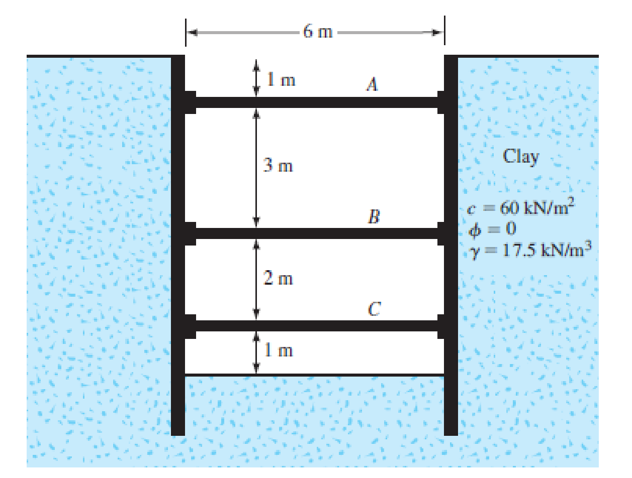
FIG. 15.51
Expert Solution & Answer

Trending nowThis is a popular solution!

Students have asked these similar questions
Q9.1 -
A 25-m high rock cut with a face angle of 60° has been excavated in a massive, very weak volcanic tuff. A tension crack has opened behind the crest and it is likely that the slope is on the point of failure, that is, the factor of safety is approx imately 1.0. The friction angle of the material is estimated to be 35°, its density is 25kN / (m ^ 3) and the position of the water table is shown on the sketch of the slope (Figure 4). The rock contains no continuous joints dipping out of the face, and the most likely type of failure mode is circular failure.
Required-
(a) Carry out a back analysis of the failure to determine the limiting value of the cohesion when the factor of safety is 1.0.
(b) Using the strength parameters calculated in (a), determine the factor of safety for a completely drained slope. Would drainage of the slope be a feasible method of stabilization?
(c) Using the ground water level shown in Figure 4 and the strength parameters calculated in (a), calculate the…
Q.1. Refer to the infinite slope shown in Figure 1. Given: β = 19 ͦ, ɣ = 20 kN/m3
, Ø = 33 ͦ,
and c’ = 47 kN/m2
. Find the height, H, such that a factor of safety, Fs = 3.1 is maintained
against sliding along the soil-rock interface.
Also Determine the thrust on the wall if the water table rises to a level 2 m below the surface
of the sand. The saturated unit weight of the sand is 20 kN/m3
.
A vertical retaining wall 6 m high is supporting a horizontal backfill having a weight of 16.5 kN/m3 and a saturated unit weight of 19kN/m3. Angle of internal friction of backfill is 30°. Ground water table is located 3m below the ground surface.
Determine the at rest lateral earth force per meter length.Determine the location of the resultant force.Determine the at rest lateral earth force per meter length if it carries a surcharge of 50 KPa.
INCLUDE FBD.
Chapter 15 Solutions
Fundamentals of Geotechnical Engineering (MindTap Course List)
Ch. 15 - Prob. 15.1PCh. 15 - Prob. 15.2PCh. 15 - Prob. 15.3PCh. 15 - Prob. 15.4PCh. 15 - Prob. 15.5PCh. 15 - Prob. 15.6PCh. 15 - Prob. 15.7PCh. 15 - Prob. 15.8PCh. 15 - Prob. 15.9PCh. 15 - Prob. 15.10P
Ch. 15 - Prob. 15.11PCh. 15 - Prob. 15.12PCh. 15 - Prob. 15.13PCh. 15 - Prob. 15.14PCh. 15 - Prob. 15.15PCh. 15 - Refer to the braced cut in Figure 15.50, for which...Ch. 15 - For the braced cut described in Problem 15.16,...Ch. 15 - Refer to Figure 15.51 in which = 17.5 kN/m3, c =...Ch. 15 - Refer to Figure 15.27a. For the braced cut, H = 6...Ch. 15 - Prob. 15.20PCh. 15 - Determine the factor of safety against bottom...Ch. 15 - Prob. 15.22PCh. 15 - The water table at a site is at 5 m below the...Ch. 15 - Prob. 15.24PCh. 15 - Prob. 15.25CTPCh. 15 - Figure 15.53 below shows a cantilever sheet pile...
Knowledge Booster


Learn more about
Need a deep-dive on the concept behind this application? Look no further. Learn more about this topic, civil-engineering and related others by exploring similar questions and additional content below.Similar questions
- A braced cut shown in Figure P19.3 is to be made to a depth of 9.0 m in a saturated clay deposit where the unit weight is 17.65 kN/m3 and the undrained shear strength is 30 kN/m2. The struts are spaced horizontally at 3.0 m center to center. Find the strut loads.arrow_forwardThe elevation and plan of a bracing system for an open cut in sand are shown in Figure 14.21. Using Pecks empirical pressure diagrams, determine the design strut loads. Given: sand = 18 kN/m3, ' = 38, x = 3 m, z = 1.25 m, and s = 3 m.arrow_forwardThe cross section of a braced cut supporting a sheet pile installation in a clay soil is shown in Figure 14.22. Given: H = 12 m, clay = 17.9 kN/m3, = 0, c = 75 kN/m2, and the center-to-center spacing of struts in plan view, s = 3 m. a. Using Pecks empirical pressure diagrams, draw the earth-pressure envelope. b. Determine the strut loads at levels A, B, and C.arrow_forward
- Determine the total active thrust, in kN/m, for a retaining wall (height 5.60 m) with horizontal backfill given the following properties: Unit weight = 17.42 kN/m3, angle of internal friction = 32 degrees, Cohesion = 11.76 kPa, Surcharge = 9.32 kPa.arrow_forwardDetermine the total active thrust, in kN/m, for a retaining wall (height 5.12 m.) with horizontal backfill given the following properties: Unit weight = 17.79 kN/m3, Angle of internal friction = 30°, Cohesion = 11.71 kPa, and Surcharge = 9.33 kPa.arrow_forwardConsider the smooth retaining wall shown in the figure below. Calculate the overturning moment at Point O in kN.m due to the surcharge only applied behind the wall. Assume that the surcharge is applied over a wide area. Consider a 1 m thickness in the out-of-plane directionarrow_forward
- A braced cut is carried out to 10 m depth at a site where the soil consists of 4 m of sand ( = 17.0 kN/m3, = 33) at the top underlain by 6 m of clay ( = 18.5 kN/m3, c = 35 kN/m2). a. What would be the average value of cohesion and the unit weight for the equivalent homogeneous soil profile? b. Show the lateral earth pressure envelope you would use in determining the strut loads.arrow_forwardUse Eq. (12.3), Figure P12.2, and the following values to determine the at-rest lateral earth force per unit length of the wall. Also find the location of the resultant. H = 5 m, H1 = 2 m, H2 = 3 m, γ = 15.5 kN/m3, γsat = 18.5 kN/m3, Φ' = 34º, c' = 0, q = 20 kN/m2, and OCR = 1.arrow_forwardFor the braced cut described in Problem 15.16, assume that all = 170 MN/m2. a. Determine the sheet pile section (section modulus) b. What is the section modulus of the wales at level A? 15.16 Refer to the braced cut in Figure 15.50, for which = 17 kN/m3, = 30, and c = 0. The struts are located at 3 m on center in the plan. Draw the earth pressure envelope and determine the strut loads at levels A, B, and C. FIG. 15.50arrow_forward
arrow_back_ios
arrow_forward_ios
Recommended textbooks for you
 Fundamentals of Geotechnical Engineering (MindTap...Civil EngineeringISBN:9781305635180Author:Braja M. Das, Nagaratnam SivakuganPublisher:Cengage Learning
 Principles of Foundation Engineering (MindTap Cou...Civil EngineeringISBN:9781305081550Author:Braja M. DasPublisher:Cengage Learning
 Principles of Geotechnical Engineering (MindTap C...Civil EngineeringISBN:9781305970939Author:Braja M. Das, Khaled SobhanPublisher:Cengage Learning
 Principles of Foundation Engineering (MindTap Cou...Civil EngineeringISBN:9781337705028Author:Braja M. Das, Nagaratnam SivakuganPublisher:Cengage Learning
Fundamentals of Geotechnical Engineering (MindTap...
Civil Engineering
ISBN:9781305635180
Author:Braja M. Das, Nagaratnam Sivakugan
Publisher:Cengage Learning
Principles of Foundation Engineering (MindTap Cou...
Civil Engineering
ISBN:9781305081550
Author:Braja M. Das
Publisher:Cengage Learning
Principles of Geotechnical Engineering (MindTap C...
Civil Engineering
ISBN:9781305970939
Author:Braja M. Das, Khaled Sobhan
Publisher:Cengage Learning
Principles of Foundation Engineering (MindTap Cou...
Civil Engineering
ISBN:9781337705028
Author:Braja M. Das, Nagaratnam Sivakugan
Publisher:Cengage Learning
How to build angle braces; Author: Country Living With The Harnish's;https://www.youtube.com/watch?v=3cKselS6rxY;License: Standard Youtube License