
Concept explainers
Videos
Design a two−pole low−pass Butterworth filter with a bandwidth of2.5 kHz. The largest capacitor value to be used is 50 pF. (Ans. Set
The design parameters of a low-pass Butterworth filter.
Answer to Problem 15.1EP
The design parameters are:
Explanation of Solution
Given Information:
Bandwidth of low-pass Butterworth filter is
Value of largest capacitor is 50 pF.
Calculation:
A general low-pass Butterworth circuit is shown below.
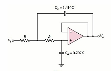
Consider
The relation between
So, the value of capacitor
dB frequency or bandwidth of the circuit is
Substituting the values,
The value of capacitor C is
So, the value of resistance R, from equation (1) is
Want to see more full solutions like this?
Chapter 15 Solutions
Microelectronics: Circuit Analysis and Design


- bessel bandpass filter analysis and all formula. lecture summaryarrow_forward3. What is the roll-off rate (per decade or per octave) for an active filter (discuss on your own words, exactly one paragaph.arrow_forwardAssume the op-amps are ideal for the filters that follow.Now; Determine the transfer functions, T(s). ii. Plot the magnitude and phase responses of each filter if R1 = 10kΩ, R2 = 100kΩ, C1 = 1μF, C2 = 0.1μF, L1 = 1nH, and L 2 = 1μH.arrow_forward
- Design a low pass active filter with a dc gain of 4 and a comer frequency of 500Hz ?arrow_forwardSince R = 500 ohms, C = 1 micro Farad and the frequency is 100 Hz in the low-pass R-C passive filter circuit, the a) Critical frequency (cutoff frequency) b) Calculate the decibel (gain) value.arrow_forwardConsider the filter circuit given in Figure 1 . a) Determine the type of the filter and justify your answer. The parameters in the circuit are R = 20Ω , C = 4pF , L = 2μH and RL =100Ω. b) Calculate the transfer function Vo/Vi with and without the load.arrow_forward
- What is the definition of Low Pass Filter, High Pass Filter and Band Pass Filter? LPF: HPF : BPF: Insert one circuit as an example for a High pass filter. HPF? List at least two applications of Band pass filters.arrow_forwardThe operational amplifier circuit shown in the figure is used as a high pass filter. Assume:C=150nF, Ro=200ΩR1 =2kΩ , R2 =6kΩDetermine:A. The Vo/Vs gain in decibels in the bandwidth.B. The cutoff frequency.arrow_forwardPlease dont copy from other websites. Design and open second order butterworth low pass filter for a cutoff frequency of 2kHz. compare the response curve with that of first order low pass filter.arrow_forward
- Draw the circuit diagrams of a first and a second order band pass filter and indicate its lower and upper cut off frequencies. Do the same for band stop filter. thanks in advance! ..arrow_forward1. Choose which basic filter response suit the signal output criteria in the figure 2. State your reason. 2. Sketch the basic filter response to suit the output citeria in Figure 2. (with labelling of passband, transition region and cut-off frequency). 3. Choose 1 type of filter if a flat pass-band gain response is required.arrow_forwardFor a basic passive RLC bandpass filter, I am calculating the values of RLC for a specific resonance frequency and bandwidth. The resistor is 1 kilo-Ohm. For a bandwidth of 600 Hz, and a resonance frequency of 2kHz, what are the values of L and C given the following equations:Bandwidth = R/Lω0 = (1/LC)^(1/2)arrow_forward
 Introductory Circuit Analysis (13th Edition)Electrical EngineeringISBN:9780133923605Author:Robert L. BoylestadPublisher:PEARSON
 Delmar's Standard Textbook Of ElectricityElectrical EngineeringISBN:9781337900348Author:Stephen L. HermanPublisher:Cengage Learning
 Programmable Logic ControllersElectrical EngineeringISBN:9780073373843Author:Frank D. PetruzellaPublisher:McGraw-Hill Education
 Fundamentals of Electric CircuitsElectrical EngineeringISBN:9780078028229Author:Charles K Alexander, Matthew SadikuPublisher:McGraw-Hill Education
 Electric Circuits. (11th Edition)Electrical EngineeringISBN:9780134746968Author:James W. Nilsson, Susan RiedelPublisher:PEARSON
 Engineering ElectromagneticsElectrical EngineeringISBN:9780078028151Author:Hayt, William H. (william Hart), Jr, BUCK, John A.Publisher:Mcgraw-hill Education,